


Adjustment
148
Index
Name
Unit
Setting range
Default value
effective
Period
0x2072
Torque
Command
Lowpass
Filter Cutoff Frequency
Hz
1-8000
8000
Immediately
N
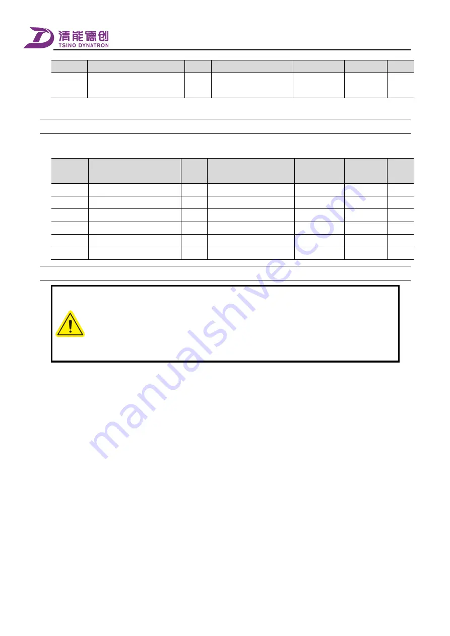
Invalid parameters in the basic mode
7.6.3
The invalid parameters in the [basic mode gain adjustment] mode are as follows.
Index
Name
Unit
Setting range
Default value
Become
effective
Period
0x21C7
Stiffness level setting
—
0-31
14
Immediately
N
0x21E1
Stiffness Level Setting 2
—
0-31
14
Immediately
N
0x21C8
Position Loop Stiffness Gain 1
0.1/s
0-65535
630
Immediately
Y
0x21C9
Position Loop Stiffness Gain 2
0.1/s
0-65535
630
Immediately
Y
0x21CA
Velocity Loop Stiffness Gain 1
0.1 Hz
0-65535
350
Immediately
Y
0x21CB
Velocity Loop Stiffness Gain 2
0.1 Hz
0-65535
350
Immediately
Y
How to use
7.6.4
1.
During the adjustment, ensure that there are no persons or other irrelevant devices in the movable
range of the mechanical moving parts, and that reliable emergency shutdown measures are in place.
2.
To guarantee the effect of system adjustment, it is recommended to use the [system parameter
identification] function to obtain the accurate load inertia ratio.
3.
When [Positioin Control Integration Time Constant 1] is set to 1000000, integration control is
invalid. The setting of invalid integration control only takes effect when the servo is OFF.
Major steps for using basic mode gain adjustment are as follows.
1.
Input the accurate [Inertia Ratio Setting] (0x20C0) or use the system parameter identification function to obtain the
accurate load inertia ratio.
2.
Set Byte0 of the parameter [Regulator Basic Control Setting] (0x21C6) to 0x00 to set the regulator to basic mode, and
restart the servo drive, so that the parameter changes take effect.
3.
Use the data tracing function of the debugging software to trace the response of the system, and then adjust relevant
parameters according to the actual needs. Each parameter is described below.
The position loop proportional gain is used to determine the response to the position loop. The bigger the value, the
better the response and the shorter the positioning time. However, due to the constraint of mechanical
characteristics, a too high value can cause positioning overshoot or mechanical jitter.
The smaller the set value of positional loop integration time constant, the stronger the integration and the better the
response to the position commands. However, a small set value might cause position loop oscillation. Increasing the
position loop integration time can reduce the overshoot of response, but a too high value can slow down the system
response.
The bigger the set value of velocity loop proportional gain, the better the response to the velocity loop. However, a
too high value can cause mechanical vibration.
Summary of Contents for CoolDrive Series
Page 29: ...Preface 17 T2 model ...
Page 30: ...Preface 18 T3 model ...
Page 31: ...Preface 19 T4 model ...
Page 230: ...Monitoring 218 ...


