


Adjustment
152
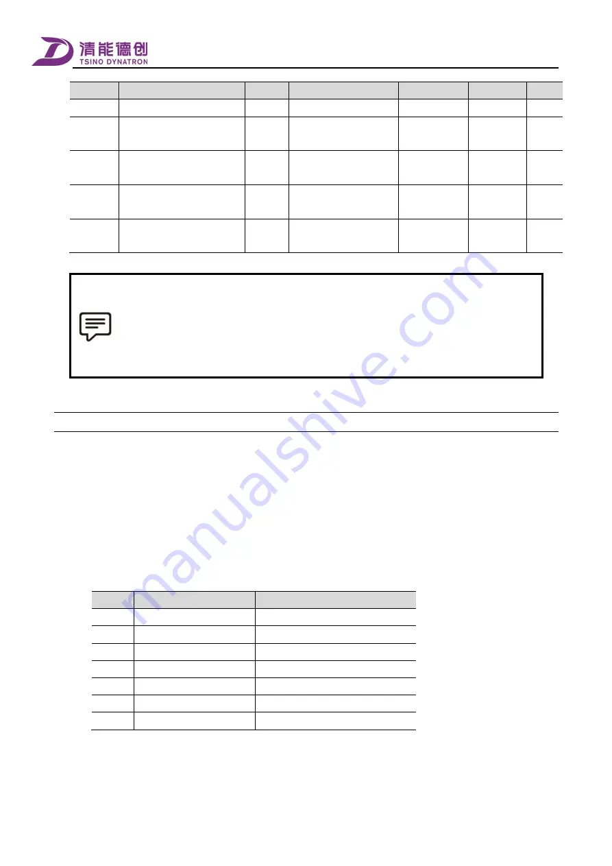
Index
Name
Unit
Setting range
Default value
effective
Period
0x21CB
Velocity Loop Stiffness Gain 2
0.1 Hz
0-65535
350
Immediately
Y
0x2165
Velocity Loop Proportional
Gain1
0.001
1-1000000
6000
Immediately
Y
0x2167
Velocity Loop Proportional
Gain2
0.001
1-1000000
4000
Immediately
Y
0x2166
Velocity Loop Integration time
Constant1
μs
125-1000000
10000
Immediately
Y
0x2168
Velocity
Loop
Integration
Time Constant2
μs
125-1000000
15000
Immediately
Y
When the [Regulator Basic Control Setting] is adopted for [basic mode], the parameters involved in
switching are [position loop proportional gain] and [velocity loop proportional gain]; when the [manual
stiffness mode] is adopted, the parameters involved in switching are [position loop stiffness gain] and
[velocity loop stiffness gain];
When the [automatic stiffness mode] is adopted, the parameters involved in switching are [stiffness level
settings] and [stiffness level settings 2].
How to use
7.7.3
The operation steps of the [adaptive gain switching] function are as follows.
1.
By adjusting the parameter [Regulator Adaptive Control Setting] (0x216B), select whether to enable the adaptive position
loop gain control and the adaptive velocity loop gain control respectively, and set the switching variables of the position
loop and the velocity loop respectively. The switching variable of the velocity loop can be different from that of the
position loop, or it can follow the adaptive position loop regulator switching variable, which means that it is the same as
the switching variable of the position loop. After the adjustment, restart the servo drive to make the parameter changes
take effect.
The details of the switching variables are shown in the following table.
Number
Switching variable
Basic value of variable
1
Torque command value
Motor rated torque
2
Velocity command value
Motor Rated Speed
3
Following error value
Encoder single-turn bits
4
Actual velocity feedback
Motor Rated Speed
5
Velocity feedforward
Motor Rated Speed
6
Acceleration feedforward
Motor Rated Speed/ms
7
Positioning completion state
——
2.
Set the first and second sets of gains of the position loop and the velocity loop respectively according to the specific
requirements.
3.
Pay attention to the following when setting the switching conditions.
Summary of Contents for CoolDrive Series
Page 29: ...Preface 17 T2 model ...
Page 30: ...Preface 18 T3 model ...
Page 31: ...Preface 19 T4 model ...
Page 230: ...Monitoring 218 ...


