


User Manual of EM730/EM730E Series Inverter
198
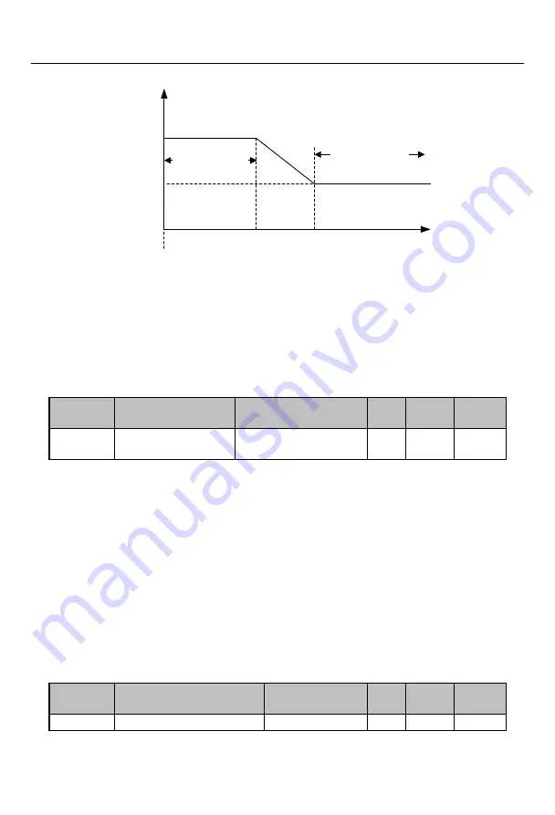
Frequency
0
Low frequency band
High frequency band
F06.28
F06.32
Injection
current
F06.29
F06.33
Fig. 7-22 Schematic Diagram of High Frequency Injection
The injection current depends on F06.29 in the low frequency band (output frequency
<F06.28) and F06.33 in the high frequency band (output frequency> F06.32).
To get better results, the gain and integral time of the regulator can be adjusted. Default
settings can be used under normal circumstances.
They must not be adjusted by non-professionals.
Function
code
Function code name
Parameter description
Unit
Default
setting
Attribute
F06.37
Stiffness coefficient of
speed loop
0~20
12
●
In the vector control mode, the dynamic speed response of the inverter is adjusted by
changing the speed proportional gain (ASR_P) and speed integral time (ASR_T) of the speed PI
regulator. The increase in ASR_P or decrease in ASR_T may accelerate the dynamic response of
the speed loop. If ASR_P is too large or ASR_T is too small, however, the system may be
over-tuned to cause oscillation.
In case of any change in F06.37, the default values of F06.00-F06.03 will change
accordingly. The adjustment intensity of the speed PI regulator can be changed. There are 21
optional groups of parameters in total. The larger the set value of F06.37, the larger the
proportional gain is, the smaller the integral time is, and the more intense the speed PID
regulation is. The smaller the set value of F06.37, the weaker the speed PID regulation is.
Function
code
Function code name
Parameter
description
Unit
Default
setting
Attribute
F06.41
Open-loop
low-frequency
0: VF
0
〇


