419050/B
533
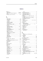
making a noise/speed curve to determine vessel
noise.................................................... 358
measuring noise at different speeds ................. 358
measuring noise in passive mode ........... 301,
measuring the DC output voltages from the
Power Supply Unit ................................... 357
mounting support brackets on the Hull
Unit............................................... 152, 170
opening the BITE (Built-In Test Equipment)
dialog box ............................................. 388
packing for storage or shipment ..................... 507
preparing a cable for termination .................... 260
restoring from a backup image on a USB flash
drive .................................................... 385
returning electronic modules to Kongsberg
Maritime ............................................... 514
returning printed circuit boards to Kongsberg
Maritime ............................................... 514
securing and terminating a cable..................... 262
selecting synchronization mode...................... 226
selecting synchronization port ....................... 225
setting to work ......................................... 266
setting up synchronization ...................... 225–226
setting up the catch sensor interface................. 330
setting up the GPS interface .......................... 328
setting up the gyro interface .......................... 324
setting up the motion reference unit (MRU)
interface................................................ 333
setting up the navigation sensor interface .......... 328
setting up the speed log interface .................... 326
setting up the trawl system interface ................ 331
starting the Processor Unit for the first time ........ 299
testing the Operating Panel to verify basic
functionality........................................... 345
testing the receiver and transmitter channels
with the BITE B-Scan page ......................... 351
transporting Kongsberg Maritime
equipment ............................................. 498
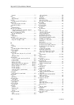
turning on ............................................... 311
turning on the system for the first time ............. 307
turning on the Transceiver Unit for the first
time..................................................... 300
unpacking a mechanical unit ......................... 504
unpacking an electromechanical unit ............... 505
unpacking an electronic unit ......................... 505
unpacking and handling electronic modules ........ 512
unpacking and handling printed circuit
boards .................................................. 512
unpacking standard parts and units .................. 503
unpacking the hull unit.......................... 148, 165
using multi-diameter cable sealing .................. 263
verifying basic functionality.......................... 349
verifying correct cable connections ................. 280
verifying ship dimensions ............................ 379
verifying that operational power is correct ......... 298
verifying the communication with the motion
reference unit (MRU) ................................ 368
verifying the GPS interface..................... 363, 367
verifying the installation parameters for the
GPS antenna .......................................... 376
verifying the installation parameters for the
transducer.............................................. 377
verifying the navigation sensor
interface.......................................... 363, 367
verifying the quality of the hull unit
installation....................................... 155, 173
verifying the quality of the installation trunk
mounting ........................................ 126, 136
verifying the quality of the mounting
flange, gate valve and transducer dock
installation....................................... 100, 118
verifying the quality of the sonar
room.............................................. 155, 173
verifying the speed log interface..................... 365
visual inspection of the computer.................... 270
visual inspection of the display ...................... 268
visual inspection of the hull unit..................... 276
visual inspection of the Operating Panel ........... 271
visual inspection of the Power Supply Unit ........ 274
visual inspection of the Processor Unit ............. 270
visual inspection of the transceiver.................. 272
visual inspection of the Transceiver Unit........... 272
visual inspection of units and transportation
boxes after arrival .................................... 500
procedures
creating mounting procedures............... 15, 53, 437
unpacking ............................................... 502
cable plan ............................................... 192
choosing the best location .............................. 62
compass safe distance ............................. 62, 400
connectors............................................... 204
environmental requirements.......................... 399
graphic adapter ......................................... 208
installation .............................................. 178
introduction ............................................... 23
outline dimensions..................................... 397
outline dimensions drawing .......................... 438
overview .................................................. 23
power requirements.................................... 395
purpose .................................................... 23
starting for the first time .............................. 299
visual inspection ....................................... 270
weight ................................................... 397
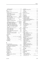
acoustic noise............................................. 78
DBS (depth of the trawl sensor) ..................... 418
FS3300 binary depth .................................. 419
Furuno CIF (sea current).............................. 429
GLL (trawl position) .................................. 419
HFB (trawl heights) ................................... 420
Kaijo VDVCD (sea current and depth) ............. 432
MDS (measured data shoal) .......................... 420
MTW (trawl temperature) ............................ 422
PSIMP-D (catch sensor data) ........................ 422
PSIMP-F (catch sensor data) ......................... 424
Ryokosei RBY (buoy data) ........................... 433
Serpe BSC (buoy data)................................ 434
TDS (trawl door distance) ............................ 425
TFI (trawl fill) .......................................... 425
TPC (trawl position in Cartesian
coordinates) ........................................... 426
TPP (tracked target position) ......................... 426
TPT (trawl bearing and water depth)................ 427
TS2 (second trawl door distance).................... 428
TTS (trawl to shoal distance)......................... 428
cable requirements..................................... 258
Index
Summary of Contents for SC90
Page 2: ......
Page 16: ...14 419050 B Simrad SC90 ...
Page 219: ...419050 B 217 Øverland UPC 3005 Dimensions Cable layout and interconnections ...
Page 223: ...419050 B 221 Øverland UPC 5000P Dimensions Cable layout and interconnections ...
Page 438: ...436 419050 B 427177 Transducer dock dimensions page 494 Simrad SC90 Installation Manual ...
Page 441: ...419050 B 439 Drawing file ...
Page 442: ...440 419050 B Simrad SC90 Installation Manual ...
Page 445: ...419050 B 443 Drawing file ...
Page 452: ...450 419050 B Simrad SC90 Installation Manual ...
Page 455: ...419050 B 453 Drawing file ...
Page 458: ...456 419050 B Simrad SC90 Installation Manual ...
Page 463: ...419050 B 461 Drawing file ...
Page 468: ...466 419050 B Simrad SC90 Installation Manual ...
Page 469: ...419050 B 467 Related topics Installing the optional gate valve DN350 page 84 Drawing file ...
Page 471: ...419050 B 469 Drawing file ...
Page 473: ...419050 B 471 214043 Gate valve installation DN350 Drawing file ...
Page 475: ...419050 B 473 422915 Gate valve installation DN350 Drawing file ...
Page 477: ...419050 B 475 083045 Gate valve installation DN500 Drawing file ...
Page 479: ...419050 B 477 33414 Gate valve dimensions DN350 Drawing file ...
Page 480: ...478 419050 B Simrad SC90 Installation Manual ...
Page 481: ...419050 B 479 Related topics Installing the optional gate valve DN350 page 84 Drawing file ...
Page 482: ...480 419050 B 33473 Gate valve dimensions DN350 Simrad SC90 Installation Manual ...
Page 483: ...419050 B 481 Related topics Installing the optional gate valve DN350 page 84 Drawing file ...
Page 484: ...482 419050 B 33498 Gate valve dimensions DN500 Simrad SC90 Installation Manual ...
Page 485: ...419050 B 483 Drawing file ...
Page 487: ...419050 B 485 37357 Gate valve dimensions DN500 Drawing file ...
Page 488: ...486 419050 B Simrad SC90 Installation Manual ...
Page 489: ...419050 B 487 Related topics Installing the optional gate valve DN500 page 103 Drawing file ...
Page 491: ...419050 B 489 Drawing file ...
Page 494: ...492 419050 B Simrad SC90 Installation Manual ...
Page 495: ...419050 B 493 Related topics Installing the optional gate valve DN350 page 84 Drawing file ...
Page 497: ...419050 B 495 Drawing file ...
Page 542: ... 2018Kongsberg Maritime ISBN xxx ...
Page 543: ......
Page 544: ...Simrad SC90 Fish finding sonar Installation Manual ...

