262
419050/B
5
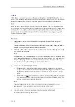
Leaving an appropriate length of the screen exposed from the insulation, cut off
the remainder.
Securing and terminating cables
Once a cable has been prepared for termination, it must be connected to a unit or cabinet.
Prerequisites
Electrical installations can only be done by certified electricians. All necessary tools and
instruments required must be available. The installation shipyard must prepare detailed
drawings of the electrical system, and identify each cable.
Context
Observe the relevant cable plans, cable lists and/or interconnection drawings for the
SC90.
Procedure
1
Referring to the wiring diagram and ensuring that there is 5 to 10 cm slack cable
inside the cabinet, prepare and connect the cable cores to the appropriate terminals
and/or plugs within or onto the cabinet.
2
Secure the cable using cable clips.
3
Check the terminal connections against the wiring diagram to ensure they are
correct. Follow the same procedure for all the cables and cable glands.
4
Check the cabinet to ensure all tools and rubbish are removed, then close the
cabinet door.
5
Take the appropriate safety measures, then replace the fuses and apply power to
the system.
6
Perform a relevant system test to ensure the installation has been made successfully.
Simrad SC90 Installation Manual
Summary of Contents for SC90
Page 2: ......
Page 16: ...14 419050 B Simrad SC90 ...
Page 219: ...419050 B 217 Øverland UPC 3005 Dimensions Cable layout and interconnections ...
Page 223: ...419050 B 221 Øverland UPC 5000P Dimensions Cable layout and interconnections ...
Page 438: ...436 419050 B 427177 Transducer dock dimensions page 494 Simrad SC90 Installation Manual ...
Page 441: ...419050 B 439 Drawing file ...
Page 442: ...440 419050 B Simrad SC90 Installation Manual ...
Page 445: ...419050 B 443 Drawing file ...
Page 452: ...450 419050 B Simrad SC90 Installation Manual ...
Page 455: ...419050 B 453 Drawing file ...
Page 458: ...456 419050 B Simrad SC90 Installation Manual ...
Page 463: ...419050 B 461 Drawing file ...
Page 468: ...466 419050 B Simrad SC90 Installation Manual ...
Page 469: ...419050 B 467 Related topics Installing the optional gate valve DN350 page 84 Drawing file ...
Page 471: ...419050 B 469 Drawing file ...
Page 473: ...419050 B 471 214043 Gate valve installation DN350 Drawing file ...
Page 475: ...419050 B 473 422915 Gate valve installation DN350 Drawing file ...
Page 477: ...419050 B 475 083045 Gate valve installation DN500 Drawing file ...
Page 479: ...419050 B 477 33414 Gate valve dimensions DN350 Drawing file ...
Page 480: ...478 419050 B Simrad SC90 Installation Manual ...
Page 481: ...419050 B 479 Related topics Installing the optional gate valve DN350 page 84 Drawing file ...
Page 482: ...480 419050 B 33473 Gate valve dimensions DN350 Simrad SC90 Installation Manual ...
Page 483: ...419050 B 481 Related topics Installing the optional gate valve DN350 page 84 Drawing file ...
Page 484: ...482 419050 B 33498 Gate valve dimensions DN500 Simrad SC90 Installation Manual ...
Page 485: ...419050 B 483 Drawing file ...
Page 487: ...419050 B 485 37357 Gate valve dimensions DN500 Drawing file ...
Page 488: ...486 419050 B Simrad SC90 Installation Manual ...
Page 489: ...419050 B 487 Related topics Installing the optional gate valve DN500 page 103 Drawing file ...
Page 491: ...419050 B 489 Drawing file ...
Page 494: ...492 419050 B Simrad SC90 Installation Manual ...
Page 495: ...419050 B 493 Related topics Installing the optional gate valve DN350 page 84 Drawing file ...
Page 497: ...419050 B 495 Drawing file ...
Page 542: ... 2018Kongsberg Maritime ISBN xxx ...
Page 543: ......
Page 544: ...Simrad SC90 Fish finding sonar Installation Manual ...

