419050/B
321
Defining the installation parameters for the transducer
Information from a few key sensors are vital for the SC90 accuracy. In order to achieve
maximum accuracy, the physical locations of these sensors - normally referred to the
Ship Origin
- must be recorded in the SC90 setup. For future reference, the offset values
for each sensor is recorded.
Prerequisites
For the accurate locations of the transducer and the
global positioning system (GPS) antenna, you need
the detailed vessel drawings. The information about
the installation angles must be retrieved from the
reports provided by the personnel that did the actual
installation.
Neither tools nor instruments are required. The SC90
is turned on, and it is working normally.
Context
The physical location of the SC90 transducer is
important for the SC90 data accuracy. The locations
of the transducer and the Global Positioning System
(GPS) antenna must be referenced to a common
Ship
Origin
. For the SC90, the
Ship Origin
is positioned
at the vessel’s stern. This is necessary to get the
Own
ship
and
Seine
markers positioned on the vessel’s track
line, which is generated from the vessel’s stern.
The physical location of the motion reference unit
(MRU) is not important for the SC90 operation. Only
the roll and pitch outputs are used, and these are not location dependant.
Procedure
1
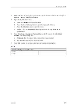
Observe the
Status
parameter dialog box in the bottom right corner of the SC90
presentation.
2
Make sure that the dialog box presents the current information from the navigation
sensors: Position, Heading and Speed.
3
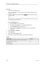
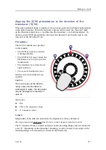
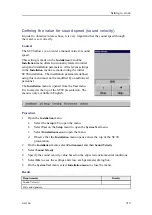
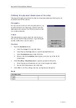
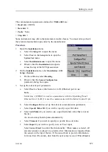
Open the
Installation
menu.
a
Select the
Setup
tab to open the menu.
b
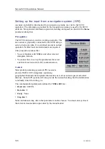
Select
Test
on the
Setup
menu to open the
System Test
menu.
c
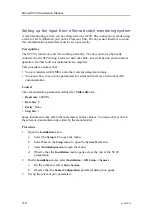
Select
Installation menu
to open the menu.
d
Observe that the
Installation
menu opens across the top of the SC90
presentation.
4
Select
OwnShip
→
Instrument Position Offsets
→
Transducer
to open the
Transducer
Offset Positions
parameter dialog box.
Summary of Contents for SC90
Page 2: ......
Page 16: ...14 419050 B Simrad SC90 ...
Page 219: ...419050 B 217 Øverland UPC 3005 Dimensions Cable layout and interconnections ...
Page 223: ...419050 B 221 Øverland UPC 5000P Dimensions Cable layout and interconnections ...
Page 438: ...436 419050 B 427177 Transducer dock dimensions page 494 Simrad SC90 Installation Manual ...
Page 441: ...419050 B 439 Drawing file ...
Page 442: ...440 419050 B Simrad SC90 Installation Manual ...
Page 445: ...419050 B 443 Drawing file ...
Page 452: ...450 419050 B Simrad SC90 Installation Manual ...
Page 455: ...419050 B 453 Drawing file ...
Page 458: ...456 419050 B Simrad SC90 Installation Manual ...
Page 463: ...419050 B 461 Drawing file ...
Page 468: ...466 419050 B Simrad SC90 Installation Manual ...
Page 469: ...419050 B 467 Related topics Installing the optional gate valve DN350 page 84 Drawing file ...
Page 471: ...419050 B 469 Drawing file ...
Page 473: ...419050 B 471 214043 Gate valve installation DN350 Drawing file ...
Page 475: ...419050 B 473 422915 Gate valve installation DN350 Drawing file ...
Page 477: ...419050 B 475 083045 Gate valve installation DN500 Drawing file ...
Page 479: ...419050 B 477 33414 Gate valve dimensions DN350 Drawing file ...
Page 480: ...478 419050 B Simrad SC90 Installation Manual ...
Page 481: ...419050 B 479 Related topics Installing the optional gate valve DN350 page 84 Drawing file ...
Page 482: ...480 419050 B 33473 Gate valve dimensions DN350 Simrad SC90 Installation Manual ...
Page 483: ...419050 B 481 Related topics Installing the optional gate valve DN350 page 84 Drawing file ...
Page 484: ...482 419050 B 33498 Gate valve dimensions DN500 Simrad SC90 Installation Manual ...
Page 485: ...419050 B 483 Drawing file ...
Page 487: ...419050 B 485 37357 Gate valve dimensions DN500 Drawing file ...
Page 488: ...486 419050 B Simrad SC90 Installation Manual ...
Page 489: ...419050 B 487 Related topics Installing the optional gate valve DN500 page 103 Drawing file ...
Page 491: ...419050 B 489 Drawing file ...
Page 494: ...492 419050 B Simrad SC90 Installation Manual ...
Page 495: ...419050 B 493 Related topics Installing the optional gate valve DN350 page 84 Drawing file ...
Page 497: ...419050 B 495 Drawing file ...
Page 542: ... 2018Kongsberg Maritime ISBN xxx ...
Page 543: ......
Page 544: ...Simrad SC90 Fish finding sonar Installation Manual ...


