419050/B
337
2
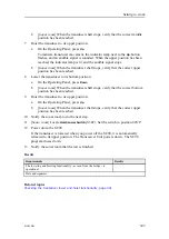
Open the
Installation
menu.
a
Select the
Setup
tab to open the menu.
b
Select
Test
on the
Setup
menu to open the
System Test
menu.
c
Select
Installation menu
to open the menu.
d
Observe that the
Installation
menu opens across the top of the SC90
presentation.
e
On the
Installation
menu, select
Installation
→
I/O Setup
→
Sensors
.
f
On the submenu, select
Stabilization
.
g
Select
External
.
h
Observe that the
Sensor Configuration
parameter dialog box opens.
3
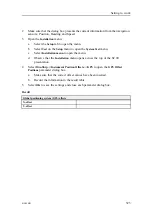
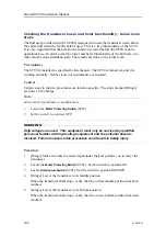
Use the surface reverberation
a
Adjust the
Tilt
to a small angle.
b
Observe the surface reverberation.
c
Steer the vessel in a circle to see if the surface reverberation is constant related
to the with course.
d
Adjust the roll offset so that reverberation appears to be identical on equal
on both sides of the vessel.
e
Adjust the pitch to make the reverberation uniform around the bow.
The aft reverberation may be influenced by the physical location of the
transducer under the hull and the wake made by the vessel.
4
Use a flat bottom
a
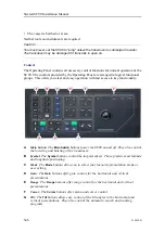
Tilt down the sonar beam to make a bottom ring appear on the SC90
presentation.
b
Use the Variable Range Marker to mark the diameter of the bottom ring.
c
Adjust roll and tilt offsets to make the bottom ring as circular as possible.
5
Select
Close
to save the settings and close the parameter dialog box.
6
Close the
Installation
menu.
Summary of Contents for SC90
Page 2: ......
Page 16: ...14 419050 B Simrad SC90 ...
Page 219: ...419050 B 217 Øverland UPC 3005 Dimensions Cable layout and interconnections ...
Page 223: ...419050 B 221 Øverland UPC 5000P Dimensions Cable layout and interconnections ...
Page 438: ...436 419050 B 427177 Transducer dock dimensions page 494 Simrad SC90 Installation Manual ...
Page 441: ...419050 B 439 Drawing file ...
Page 442: ...440 419050 B Simrad SC90 Installation Manual ...
Page 445: ...419050 B 443 Drawing file ...
Page 452: ...450 419050 B Simrad SC90 Installation Manual ...
Page 455: ...419050 B 453 Drawing file ...
Page 458: ...456 419050 B Simrad SC90 Installation Manual ...
Page 463: ...419050 B 461 Drawing file ...
Page 468: ...466 419050 B Simrad SC90 Installation Manual ...
Page 469: ...419050 B 467 Related topics Installing the optional gate valve DN350 page 84 Drawing file ...
Page 471: ...419050 B 469 Drawing file ...
Page 473: ...419050 B 471 214043 Gate valve installation DN350 Drawing file ...
Page 475: ...419050 B 473 422915 Gate valve installation DN350 Drawing file ...
Page 477: ...419050 B 475 083045 Gate valve installation DN500 Drawing file ...
Page 479: ...419050 B 477 33414 Gate valve dimensions DN350 Drawing file ...
Page 480: ...478 419050 B Simrad SC90 Installation Manual ...
Page 481: ...419050 B 479 Related topics Installing the optional gate valve DN350 page 84 Drawing file ...
Page 482: ...480 419050 B 33473 Gate valve dimensions DN350 Simrad SC90 Installation Manual ...
Page 483: ...419050 B 481 Related topics Installing the optional gate valve DN350 page 84 Drawing file ...
Page 484: ...482 419050 B 33498 Gate valve dimensions DN500 Simrad SC90 Installation Manual ...
Page 485: ...419050 B 483 Drawing file ...
Page 487: ...419050 B 485 37357 Gate valve dimensions DN500 Drawing file ...
Page 488: ...486 419050 B Simrad SC90 Installation Manual ...
Page 489: ...419050 B 487 Related topics Installing the optional gate valve DN500 page 103 Drawing file ...
Page 491: ...419050 B 489 Drawing file ...
Page 494: ...492 419050 B Simrad SC90 Installation Manual ...
Page 495: ...419050 B 493 Related topics Installing the optional gate valve DN350 page 84 Drawing file ...
Page 497: ...419050 B 495 Drawing file ...
Page 542: ... 2018Kongsberg Maritime ISBN xxx ...
Page 543: ......
Page 544: ...Simrad SC90 Fish finding sonar Installation Manual ...

