522
419050/B
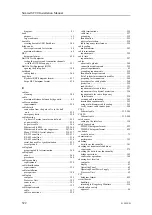
diagram.................................................... 21
purpose .................................................... 15
target audience ........................................... 15
creating bootable USB flash drive ................... 386
basic requirements for location ........................ 59
maximum distances...................................... 60
datagram format........................................ 434
testing the receiver and transmitter channels
with the BITE B-Scan page ......................... 351
Built In Test Equipment (BITE)
opening the dialog box ................................ 388
cable glands............................................. 260
Ryokosei RBY datagram format..................... 433
Serpe BSC datagram format.......................... 434
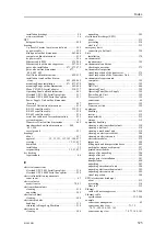
C
cleaning ................................................. 508
maximum distance between bridge units ............. 60
requirements ............................................ 259
connection from the gate valve to the hull
unit ..................................................... 252
emergency hoist ........................................ 250
3–phase AC mains to motor control unit ........... 249
ac power cable.......................................... 229
dc power cable ......................................... 246
Ethernet cable RJ45 ............................. 239–240
Ethernet cable with noise suppressor.......... 247–248
Moxa CP114EL-I serial adapter ............... 210, 237
RS-232 serial line ................................ 232–233
RS-422 serial line ...................................... 234
RS-485 serial line ...................................... 236
serial line used for synchronization ................. 235
vessel ground ........................................... 231
preparing cable for termination ...................... 260
about ..................................................... 260
procedures .............................................. 260
requirements ............................................ 259
requirements ............................................ 259
prerequisites ............................................ 198
computer ................................................ 192
Processor Unit.......................................... 192
sonar room .............................................. 193
topside ................................................... 192
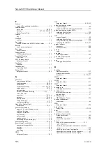
cable ..................................................... 257
cable connections ...................................... 259
cable terminations ..................................... 259
cable trays............................................... 257
grounding ............................................... 259
identification............................................ 259
physical protection..................................... 258
radio frequency interference.......................... 258
multi-diameter.......................................... 263
requirements ............................................ 259
requirements ............................................ 257
about cable glands ..................................... 260
connection requirements .............................. 259
general requirements .................................... 45
grounding requirements............................... 259
identification requirements ........................... 259
list of system interconnection cables ................ 195
preparing for termination ............................. 260
procedures for cable glands .......................... 260
protection ............................................... 258
read this first ............................................ 191
requirements for cable trays .......................... 257
requirements for physical protection ................ 258
requirements for radio frequency
interference............................................ 258
securing and terminating.............................. 262
termination requirements ............................. 259
using multi-diameter cable sealing .................. 263
verify correct cable connections ..................... 280
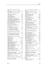
CAT5
Ethernet cable .................................... 239–240
CAT5E
Ethernet cable .................................... 239–240
setting up the interface ................................ 330
PSIMP-D datagram format ........................... 422
PSIMP-F datagram format............................ 424
acoustic noise............................................. 79
performance ............................................ 392
hoist/lower functionality .............................. 341
checking environmental conditions
sonar room .............................................. 279
checking the hoist/lower functionality
bridge operations....................................... 342
sonar room operations................................. 344
computer .................................................. 62
display ..................................................... 61
Operating Panel .......................................... 62
Operating Panel Power Supply ........................ 62
Processor Unit............................................ 62
datagram format........................................ 429
handling ................................................. 512
returning to Kongsberg Maritime.................... 514
approval ................................................... 46
Simrad SC90 Installation Manual
Summary of Contents for SC90
Page 2: ......
Page 16: ...14 419050 B Simrad SC90 ...
Page 219: ...419050 B 217 Øverland UPC 3005 Dimensions Cable layout and interconnections ...
Page 223: ...419050 B 221 Øverland UPC 5000P Dimensions Cable layout and interconnections ...
Page 438: ...436 419050 B 427177 Transducer dock dimensions page 494 Simrad SC90 Installation Manual ...
Page 441: ...419050 B 439 Drawing file ...
Page 442: ...440 419050 B Simrad SC90 Installation Manual ...
Page 445: ...419050 B 443 Drawing file ...
Page 452: ...450 419050 B Simrad SC90 Installation Manual ...
Page 455: ...419050 B 453 Drawing file ...
Page 458: ...456 419050 B Simrad SC90 Installation Manual ...
Page 463: ...419050 B 461 Drawing file ...
Page 468: ...466 419050 B Simrad SC90 Installation Manual ...
Page 469: ...419050 B 467 Related topics Installing the optional gate valve DN350 page 84 Drawing file ...
Page 471: ...419050 B 469 Drawing file ...
Page 473: ...419050 B 471 214043 Gate valve installation DN350 Drawing file ...
Page 475: ...419050 B 473 422915 Gate valve installation DN350 Drawing file ...
Page 477: ...419050 B 475 083045 Gate valve installation DN500 Drawing file ...
Page 479: ...419050 B 477 33414 Gate valve dimensions DN350 Drawing file ...
Page 480: ...478 419050 B Simrad SC90 Installation Manual ...
Page 481: ...419050 B 479 Related topics Installing the optional gate valve DN350 page 84 Drawing file ...
Page 482: ...480 419050 B 33473 Gate valve dimensions DN350 Simrad SC90 Installation Manual ...
Page 483: ...419050 B 481 Related topics Installing the optional gate valve DN350 page 84 Drawing file ...
Page 484: ...482 419050 B 33498 Gate valve dimensions DN500 Simrad SC90 Installation Manual ...
Page 485: ...419050 B 483 Drawing file ...
Page 487: ...419050 B 485 37357 Gate valve dimensions DN500 Drawing file ...
Page 488: ...486 419050 B Simrad SC90 Installation Manual ...
Page 489: ...419050 B 487 Related topics Installing the optional gate valve DN500 page 103 Drawing file ...
Page 491: ...419050 B 489 Drawing file ...
Page 494: ...492 419050 B Simrad SC90 Installation Manual ...
Page 495: ...419050 B 493 Related topics Installing the optional gate valve DN350 page 84 Drawing file ...
Page 497: ...419050 B 495 Drawing file ...
Page 542: ... 2018Kongsberg Maritime ISBN xxx ...
Page 543: ......
Page 544: ...Simrad SC90 Fish finding sonar Installation Manual ...

