


334
419050/B
A
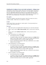
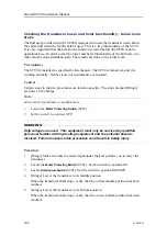
Bow & 0
°
motion sensor
B
This is the offset angle
C
0
°
transducer mark
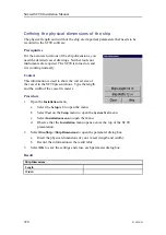
Procedure
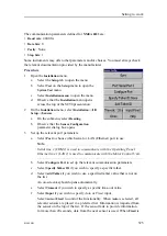
1
Select the
Setup
tab to
open the menu.
2
Select
Test
on the
Setup
menu to open the
System
Test
menu.
a
Write down the roll
compensation value
in the
Roll
"button".
b
Write down the pitch
compensation value
in the
Pitch
"button".
3
Open the
Installation
menu.
a
Select the
Setup
tab
to open the menu.
b
Select
Test
on the
Setup
menu to open
the
System Test
menu.
c
Select
Installation
menu
to open the
menu.
d
Observe that the
Installation
menu opens across the top of the SC90
presentation.
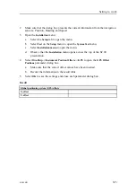
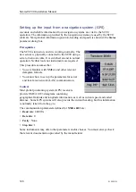
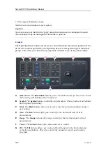
4
On the
Installation
menu, select
Installation
→
I/O Setup
→
Sensors
.
a
On the submenu, select
Stabilization
.
b
Select
External
.
c
Observe that the
Sensor Configuration
parameter dialog box opens.
d
Select the serial port you wish to use.
e
Set up the relevant port parameters.
f
Specify the timeout value.
g
Specify if the input shall be
Automatic
or
Fixed
.
h
Select
Close
to save the settings and close the parameter dialog box.
Note
Once you close the
Sensor Configuration
parameter dialog, the chosen
communication port will "disappear".
If you later need to change
the communication parameters, you must first choose internal sensor
(select Transceiver1), and then restart the SC90.
Simrad SC90 Installation Manual
Summary of Contents for SC90
Page 2: ......
Page 16: ...14 419050 B Simrad SC90 ...
Page 219: ...419050 B 217 Øverland UPC 3005 Dimensions Cable layout and interconnections ...
Page 223: ...419050 B 221 Øverland UPC 5000P Dimensions Cable layout and interconnections ...
Page 438: ...436 419050 B 427177 Transducer dock dimensions page 494 Simrad SC90 Installation Manual ...
Page 441: ...419050 B 439 Drawing file ...
Page 442: ...440 419050 B Simrad SC90 Installation Manual ...
Page 445: ...419050 B 443 Drawing file ...
Page 452: ...450 419050 B Simrad SC90 Installation Manual ...
Page 455: ...419050 B 453 Drawing file ...
Page 458: ...456 419050 B Simrad SC90 Installation Manual ...
Page 463: ...419050 B 461 Drawing file ...
Page 468: ...466 419050 B Simrad SC90 Installation Manual ...
Page 469: ...419050 B 467 Related topics Installing the optional gate valve DN350 page 84 Drawing file ...
Page 471: ...419050 B 469 Drawing file ...
Page 473: ...419050 B 471 214043 Gate valve installation DN350 Drawing file ...
Page 475: ...419050 B 473 422915 Gate valve installation DN350 Drawing file ...
Page 477: ...419050 B 475 083045 Gate valve installation DN500 Drawing file ...
Page 479: ...419050 B 477 33414 Gate valve dimensions DN350 Drawing file ...
Page 480: ...478 419050 B Simrad SC90 Installation Manual ...
Page 481: ...419050 B 479 Related topics Installing the optional gate valve DN350 page 84 Drawing file ...
Page 482: ...480 419050 B 33473 Gate valve dimensions DN350 Simrad SC90 Installation Manual ...
Page 483: ...419050 B 481 Related topics Installing the optional gate valve DN350 page 84 Drawing file ...
Page 484: ...482 419050 B 33498 Gate valve dimensions DN500 Simrad SC90 Installation Manual ...
Page 485: ...419050 B 483 Drawing file ...
Page 487: ...419050 B 485 37357 Gate valve dimensions DN500 Drawing file ...
Page 488: ...486 419050 B Simrad SC90 Installation Manual ...
Page 489: ...419050 B 487 Related topics Installing the optional gate valve DN500 page 103 Drawing file ...
Page 491: ...419050 B 489 Drawing file ...
Page 494: ...492 419050 B Simrad SC90 Installation Manual ...
Page 495: ...419050 B 493 Related topics Installing the optional gate valve DN350 page 84 Drawing file ...
Page 497: ...419050 B 495 Drawing file ...
Page 542: ... 2018Kongsberg Maritime ISBN xxx ...
Page 543: ......
Page 544: ...Simrad SC90 Fish finding sonar Installation Manual ...