419050/B
305
Connecting the transducer cables to the Transceiver Unit
The transducer cables are connected to the Transceiver Unit using a large transceiver
plug. The transceiver plug must be firmly connected to the side socket on the Transceiver
Unit - and the transducer must be submerged in water - before you can transmitting
(‘pinging’) with the SC90.
Prerequisites
We assume that you are equipped with a standard set of tools.
This tool set must comprise the normal tools for electronic and
electromechanical tasks. Each tool must be provided in various
sizes. We recommend that all tools are demagnetized to protect
your equipment.
Context
Once the transceiver plug is connected to the Transceiver Unit,
and the transducer is submerged in water, the SC90 can be set
to transmit ("ping").
Caution
You must never start SC90 transmissions ("pinging") when
the ship is in dry dock. The transducer may be damaged if it
transmits in open air.
Procedure
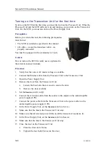
1
Make sure that the plug housing is clean and not damaged
in any way.
2
Make sure that the gasket is clean and not damaged in
any way.
3
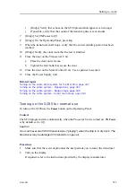
Mount the transceiver plug.
a
Hold the plug housing on top of the socket.
b
Push the plug gently in place.
To avoid unnecessary strain on the connectors, you must insert the transceiver
plug straight in.
c
Insert the bolts carefully, and make sure that they fit to the threads.
Use the bolts and washers provided for the protecting cover.
Summary of Contents for SC90
Page 2: ......
Page 16: ...14 419050 B Simrad SC90 ...
Page 219: ...419050 B 217 Øverland UPC 3005 Dimensions Cable layout and interconnections ...
Page 223: ...419050 B 221 Øverland UPC 5000P Dimensions Cable layout and interconnections ...
Page 438: ...436 419050 B 427177 Transducer dock dimensions page 494 Simrad SC90 Installation Manual ...
Page 441: ...419050 B 439 Drawing file ...
Page 442: ...440 419050 B Simrad SC90 Installation Manual ...
Page 445: ...419050 B 443 Drawing file ...
Page 452: ...450 419050 B Simrad SC90 Installation Manual ...
Page 455: ...419050 B 453 Drawing file ...
Page 458: ...456 419050 B Simrad SC90 Installation Manual ...
Page 463: ...419050 B 461 Drawing file ...
Page 468: ...466 419050 B Simrad SC90 Installation Manual ...
Page 469: ...419050 B 467 Related topics Installing the optional gate valve DN350 page 84 Drawing file ...
Page 471: ...419050 B 469 Drawing file ...
Page 473: ...419050 B 471 214043 Gate valve installation DN350 Drawing file ...
Page 475: ...419050 B 473 422915 Gate valve installation DN350 Drawing file ...
Page 477: ...419050 B 475 083045 Gate valve installation DN500 Drawing file ...
Page 479: ...419050 B 477 33414 Gate valve dimensions DN350 Drawing file ...
Page 480: ...478 419050 B Simrad SC90 Installation Manual ...
Page 481: ...419050 B 479 Related topics Installing the optional gate valve DN350 page 84 Drawing file ...
Page 482: ...480 419050 B 33473 Gate valve dimensions DN350 Simrad SC90 Installation Manual ...
Page 483: ...419050 B 481 Related topics Installing the optional gate valve DN350 page 84 Drawing file ...
Page 484: ...482 419050 B 33498 Gate valve dimensions DN500 Simrad SC90 Installation Manual ...
Page 485: ...419050 B 483 Drawing file ...
Page 487: ...419050 B 485 37357 Gate valve dimensions DN500 Drawing file ...
Page 488: ...486 419050 B Simrad SC90 Installation Manual ...
Page 489: ...419050 B 487 Related topics Installing the optional gate valve DN500 page 103 Drawing file ...
Page 491: ...419050 B 489 Drawing file ...
Page 494: ...492 419050 B Simrad SC90 Installation Manual ...
Page 495: ...419050 B 493 Related topics Installing the optional gate valve DN350 page 84 Drawing file ...
Page 497: ...419050 B 495 Drawing file ...
Page 542: ... 2018Kongsberg Maritime ISBN xxx ...
Page 543: ......
Page 544: ...Simrad SC90 Fish finding sonar Installation Manual ...


