419050/B
201
6
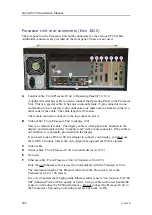
Connect the serial cables from the Processor Unit to the relevant external devices.
(C13)
For more information, see the cable details:
•
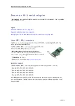
Processor Unit serial adapter, page 210
•
RS-232 serial line connection using three wires, page 232
•
RS-232 serial line connection using five wires, page 233
•
RS-422 serial line connection using five wires, page 234
•
RS-232 used as synchronization trigger (input or output), page 235
•
RS-485 serial line connection using two or four wires, page 236
•
Moxa CP114EL-I Serial line adapter, page 237
•
7
If applicable, connect the signal cable from the Processor Unit to the synchronization
system. (C13)
For more information, see the cable details:
•
K-Sync interface to generic RS-232 synchronization input, page 241
•
Simrad TU40 interface to generic RS-232 synchronization input, page 243
8
If applicable, make the relevant connections to enable the "Emergency hoist"
functionality.
Emergency hoist functionality is provided by the Hull Unit Control circuit board in
the Motor Control Unit. We does not offer any optional products or kits to put this
functionality to use. In order to use the emergency hoist functionality you will need
to design your own interface and switch box.
For more information, see the cable details:
•
Emergency hoist connections, page 250
Related topics
Processor Unit rear connectors (Enix 3820), page 204
Installing the SC90 cables, page 198
Processor Unit serial adapter, page 210
Serial line splitters, page 213
Basic cable requirements, page 257
Setting up the SC90 in a synchronized system, page 222
Summary of Contents for SC90
Page 2: ......
Page 16: ...14 419050 B Simrad SC90 ...
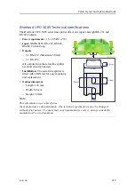
Page 219: ...419050 B 217 Øverland UPC 3005 Dimensions Cable layout and interconnections ...
Page 223: ...419050 B 221 Øverland UPC 5000P Dimensions Cable layout and interconnections ...
Page 438: ...436 419050 B 427177 Transducer dock dimensions page 494 Simrad SC90 Installation Manual ...
Page 441: ...419050 B 439 Drawing file ...
Page 442: ...440 419050 B Simrad SC90 Installation Manual ...
Page 445: ...419050 B 443 Drawing file ...
Page 452: ...450 419050 B Simrad SC90 Installation Manual ...
Page 455: ...419050 B 453 Drawing file ...
Page 458: ...456 419050 B Simrad SC90 Installation Manual ...
Page 463: ...419050 B 461 Drawing file ...
Page 468: ...466 419050 B Simrad SC90 Installation Manual ...
Page 469: ...419050 B 467 Related topics Installing the optional gate valve DN350 page 84 Drawing file ...
Page 471: ...419050 B 469 Drawing file ...
Page 473: ...419050 B 471 214043 Gate valve installation DN350 Drawing file ...
Page 475: ...419050 B 473 422915 Gate valve installation DN350 Drawing file ...
Page 477: ...419050 B 475 083045 Gate valve installation DN500 Drawing file ...
Page 479: ...419050 B 477 33414 Gate valve dimensions DN350 Drawing file ...
Page 480: ...478 419050 B Simrad SC90 Installation Manual ...
Page 481: ...419050 B 479 Related topics Installing the optional gate valve DN350 page 84 Drawing file ...
Page 482: ...480 419050 B 33473 Gate valve dimensions DN350 Simrad SC90 Installation Manual ...
Page 483: ...419050 B 481 Related topics Installing the optional gate valve DN350 page 84 Drawing file ...
Page 484: ...482 419050 B 33498 Gate valve dimensions DN500 Simrad SC90 Installation Manual ...
Page 485: ...419050 B 483 Drawing file ...
Page 487: ...419050 B 485 37357 Gate valve dimensions DN500 Drawing file ...
Page 488: ...486 419050 B Simrad SC90 Installation Manual ...
Page 489: ...419050 B 487 Related topics Installing the optional gate valve DN500 page 103 Drawing file ...
Page 491: ...419050 B 489 Drawing file ...
Page 494: ...492 419050 B Simrad SC90 Installation Manual ...
Page 495: ...419050 B 493 Related topics Installing the optional gate valve DN350 page 84 Drawing file ...
Page 497: ...419050 B 495 Drawing file ...
Page 542: ... 2018Kongsberg Maritime ISBN xxx ...
Page 543: ......
Page 544: ...Simrad SC90 Fish finding sonar Installation Manual ...


