534
419050/B
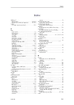
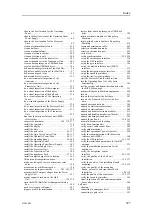
datagram format........................................ 422
datagram format........................................ 424
purpose .................................................... 15
target audience ........................................... 15
sonar room requirement................................. 67
sonar room ................................................ 67
computer .................................................. 23
display ..................................................... 22
gate valve ........................................... 85, 104
Hull Unit ............................................ 26, 282
Operating Panel .......................................... 25
Power Supply Unit ...................................... 26
Processor Unit............................................ 23
serial line splitters...................................... 213
sonar room ................................................ 64
this manual................................................ 15
Transceiver Unit ......................................... 24
transducer ................................................. 29
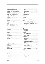
Q
quality check
hull unit installation ............................. 155, 173
installation trunk mounting ..................... 126, 136
mounting flange, gate valve and transducer
dock installation ................................ 100, 118
sonar room ........................................ 155, 173
R
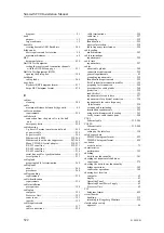
cable requirements..................................... 258
acoustic noise............................................. 80
datagram format........................................ 433
this manual................................................ 15
general supply conditions............................. 519
global positioning system............................... 40
before you power up..................................... 17
important .................................................. 17
support if something breaks down..................... 18
when the system not in use ............................. 18
when you are docking your vessel..................... 18
when you wish to switch off ........................... 18
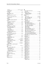
synchronization using Clear To Send (CTS)
and Request To Send (RTS) signals ............... 224
compass ................................................... 37
course gyro ............................................... 37
display ..................................................... 34
heading sensor............................................ 37
speed log .................................................. 36
uninterruptible power supply........................... 35
not provided with the delivery ......................... 34
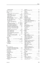
skills of installation personnel ......................... 55
ac mains power......................................... 395
approval by classification society...................... 46
cable connections ...................................... 259
cable grounding ........................................ 259
cable identification..................................... 259
cable terminations ..................................... 259
cable trays............................................... 257
cables and wiring .................................. 45, 257
cheading sensor .......................................... 37
compass ................................................... 37
compass deviation ....................................... 45
course gyro ............................................... 37
display ................................................... 401
distance between bridge units .......................... 60
dry docking ............................................... 46
environmental .......................................... 399
humidity................................................. 399
location of bridge units.................................. 59
mains power ............................................ 395
motion reference unit (MRU) interface ............... 41
noise sources ............................................. 45
physical protection of cables ......................... 258
power .................................................... 395
radio frequency interference.......................... 258
speed log interface ....................................... 36
supply power ....................................... 44, 395
temperature ............................................. 399
uninterruptible power supply...................... 35, 44
compass deviation ....................................... 45
equipment ............................................... 519
installation drawings ......................... 15, 53, 437
mounting procedures ......................... 15, 53, 437
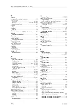
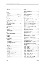
backup image........................................... 385
electronic modules..................................... 514
printed circuit boards .................................. 514
acoustic noise............................................. 81
cable requirements..................................... 258
RJ45
Ethernet cable .................................... 239–240
Ethernet cable with noise suppressor.......... 247–248
datagram format........................................ 413
multi-diameter cable sealing ......................... 263
about ..................................................... 254
Moxa CP114EL-I serial adapter ............... 210, 237
serial line cable................................... 232–233
serial line cable used for synchronization .......... 235
synchronization .................................. 241, 243
RS-422
Moxa CP114EL-I serial adapter ............... 210, 237
serial line cable......................................... 234
about ..................................................... 254
Simrad SC90 Installation Manual
Summary of Contents for SC90
Page 2: ......
Page 16: ...14 419050 B Simrad SC90 ...
Page 219: ...419050 B 217 Øverland UPC 3005 Dimensions Cable layout and interconnections ...
Page 223: ...419050 B 221 Øverland UPC 5000P Dimensions Cable layout and interconnections ...
Page 438: ...436 419050 B 427177 Transducer dock dimensions page 494 Simrad SC90 Installation Manual ...
Page 441: ...419050 B 439 Drawing file ...
Page 442: ...440 419050 B Simrad SC90 Installation Manual ...
Page 445: ...419050 B 443 Drawing file ...
Page 452: ...450 419050 B Simrad SC90 Installation Manual ...
Page 455: ...419050 B 453 Drawing file ...
Page 458: ...456 419050 B Simrad SC90 Installation Manual ...
Page 463: ...419050 B 461 Drawing file ...
Page 468: ...466 419050 B Simrad SC90 Installation Manual ...
Page 469: ...419050 B 467 Related topics Installing the optional gate valve DN350 page 84 Drawing file ...
Page 471: ...419050 B 469 Drawing file ...
Page 473: ...419050 B 471 214043 Gate valve installation DN350 Drawing file ...
Page 475: ...419050 B 473 422915 Gate valve installation DN350 Drawing file ...
Page 477: ...419050 B 475 083045 Gate valve installation DN500 Drawing file ...
Page 479: ...419050 B 477 33414 Gate valve dimensions DN350 Drawing file ...
Page 480: ...478 419050 B Simrad SC90 Installation Manual ...
Page 481: ...419050 B 479 Related topics Installing the optional gate valve DN350 page 84 Drawing file ...
Page 482: ...480 419050 B 33473 Gate valve dimensions DN350 Simrad SC90 Installation Manual ...
Page 483: ...419050 B 481 Related topics Installing the optional gate valve DN350 page 84 Drawing file ...
Page 484: ...482 419050 B 33498 Gate valve dimensions DN500 Simrad SC90 Installation Manual ...
Page 485: ...419050 B 483 Drawing file ...
Page 487: ...419050 B 485 37357 Gate valve dimensions DN500 Drawing file ...
Page 488: ...486 419050 B Simrad SC90 Installation Manual ...
Page 489: ...419050 B 487 Related topics Installing the optional gate valve DN500 page 103 Drawing file ...
Page 491: ...419050 B 489 Drawing file ...
Page 494: ...492 419050 B Simrad SC90 Installation Manual ...
Page 495: ...419050 B 493 Related topics Installing the optional gate valve DN350 page 84 Drawing file ...
Page 497: ...419050 B 495 Drawing file ...
Page 542: ... 2018Kongsberg Maritime ISBN xxx ...
Page 543: ......
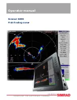
Page 544: ...Simrad SC90 Fish finding sonar Installation Manual ...


