419050/B
29
Transducer description
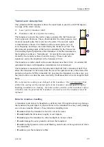
The cylindrical SC90 transducer allows the sonar beam to provide a full 360 degrees
coverage of the water volume.
A
Lower part of transducer shaft
B
Transducer with its red protective coating
The transducer converts the electric energy generated by the Transceiver
Unit to physical vibrations. These vibrations alter the water pressure, and
create an acoustic pulse that is sent into the water. The acoustic signal
is transmitted as a beam. The duration of the acoustic pulse, as well
as its frequency and shape, are controlled by the Transceiver Unit. The
direction and opening angle of the beam is controlled by the Transceiver
Unit and the physical properties of the transducer. After the transmission,
the transducer works as a "microphone". It converts the water pressure
created by the acoustic echoes to electric energy. These weak echo
signals are sent to the amplifiers in the Transceiver Unit.
The transducer is rather small with an outer diameter less than 20 cm. It contains 480
individual elements with impedance transformers for each element.
The transducer is mounted at the bottom end of the Hull Unit’s transducer shaft. This
allows the transducer to be lowered into the water for operational use, and retracted for
protection when the SC90 is turned off. By lowering the transducer into the water, you
may also be able to reduce the noise created by the laminar flow of water along the hull.
Note
The red protective coating is an vital part of the transducer. It is very important that
neither this coating nor the internal parts of the transducer are damaged during the
handling, installation or cleaning. Any holes and/or scratches in the transducer surface
will allow water to penetrate the transducer. If a leak occurs, the transducer must be
replaced.
Rules for transducer handling
A transducer must always be handled as a delicate item. Wrongful actions may damage
the transducer beyond repair. A physical blow to the transducer face may easily damage
one or more elements. Observe these transducer handling rules:
•
Do not
activate the transducer when it is out of the water.
•
Do not
handle the transducer roughly, avoid impacts.
•
Do not
expose the transducer to direct sunlight or excessive heat.
•
Do not
damage the outer protective skin on the transducer.
•
Do not
use high pressure water, sand blasting, metal tools or strong solvents to clean
the transducer.
•
Do not
step on the transducer cables.
Summary of Contents for SC90
Page 2: ......
Page 16: ...14 419050 B Simrad SC90 ...
Page 219: ...419050 B 217 Øverland UPC 3005 Dimensions Cable layout and interconnections ...
Page 223: ...419050 B 221 Øverland UPC 5000P Dimensions Cable layout and interconnections ...
Page 438: ...436 419050 B 427177 Transducer dock dimensions page 494 Simrad SC90 Installation Manual ...
Page 441: ...419050 B 439 Drawing file ...
Page 442: ...440 419050 B Simrad SC90 Installation Manual ...
Page 445: ...419050 B 443 Drawing file ...
Page 452: ...450 419050 B Simrad SC90 Installation Manual ...
Page 455: ...419050 B 453 Drawing file ...
Page 458: ...456 419050 B Simrad SC90 Installation Manual ...
Page 463: ...419050 B 461 Drawing file ...
Page 468: ...466 419050 B Simrad SC90 Installation Manual ...
Page 469: ...419050 B 467 Related topics Installing the optional gate valve DN350 page 84 Drawing file ...
Page 471: ...419050 B 469 Drawing file ...
Page 473: ...419050 B 471 214043 Gate valve installation DN350 Drawing file ...
Page 475: ...419050 B 473 422915 Gate valve installation DN350 Drawing file ...
Page 477: ...419050 B 475 083045 Gate valve installation DN500 Drawing file ...
Page 479: ...419050 B 477 33414 Gate valve dimensions DN350 Drawing file ...
Page 480: ...478 419050 B Simrad SC90 Installation Manual ...
Page 481: ...419050 B 479 Related topics Installing the optional gate valve DN350 page 84 Drawing file ...
Page 482: ...480 419050 B 33473 Gate valve dimensions DN350 Simrad SC90 Installation Manual ...
Page 483: ...419050 B 481 Related topics Installing the optional gate valve DN350 page 84 Drawing file ...
Page 484: ...482 419050 B 33498 Gate valve dimensions DN500 Simrad SC90 Installation Manual ...
Page 485: ...419050 B 483 Drawing file ...
Page 487: ...419050 B 485 37357 Gate valve dimensions DN500 Drawing file ...
Page 488: ...486 419050 B Simrad SC90 Installation Manual ...
Page 489: ...419050 B 487 Related topics Installing the optional gate valve DN500 page 103 Drawing file ...
Page 491: ...419050 B 489 Drawing file ...
Page 494: ...492 419050 B Simrad SC90 Installation Manual ...
Page 495: ...419050 B 493 Related topics Installing the optional gate valve DN350 page 84 Drawing file ...
Page 497: ...419050 B 495 Drawing file ...
Page 542: ... 2018Kongsberg Maritime ISBN xxx ...
Page 543: ......
Page 544: ...Simrad SC90 Fish finding sonar Installation Manual ...


