419050/B
529
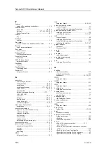
setting up navigation sensor interface............... 328
setting up the catch sensor interface................. 330
setting up the gyro interface .......................... 324
setting up the motion reference unit (MRU)
interface................................................ 333
setting up the speed log interface .................... 326
setting up the trawl system interface ................ 331
verifying motion reference unit (MRU)
interface................................................ 368
verifying the GPS interface..................... 363, 367
verifying the navigation sensor
interface.......................................... 363, 367
verifying the speed log interface..................... 365
compass ................................................... 37
course gyro ............................................... 37
heading sensor............................................ 37
motion reference unit (MRU) .......................... 41
speed log .................................................. 36
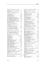
computer ................................................ 204
Øverland UPC-3005 Serial line splitter............. 216
Øverland UPC-5000P Serial line splitter ........... 220
Power Supply Unit .................................... 207
Processor Unit.......................................... 204
Transceiver Unit ....................................... 206
acoustic noise............................................. 80
cable requirements..................................... 258
electrical noise ...................................... 78, 81
computer .................................................. 23
display ..................................................... 22
gate valve ........................................... 85, 104
Hull Unit ............................................ 26, 282
Operating Panel .......................................... 25
Power Supply Unit ...................................... 26
Processor Unit............................................ 23
serial line splitters...................................... 213
sonar room ................................................ 64
Transceiver Unit ......................................... 24
transducer ................................................. 29
K
K-Sync
synchronization using RS-232 serial
line ............................................... 241, 243
datagram format........................................ 432
system ..................................................... 20
support .................................................... 47
L
required item ............................................. 34
environmental requirements.......................... 399
installation .............................................. 177
minimum requirements ............................... 401
outline dimensions..................................... 397
power requirements.................................... 395
weight ................................................... 397
lifting
hull unit ........................................... 148, 165
transportation boxes ................................... 499
unit ....................................................... 499
sonar room ................................................ 68
sonar room ................................................ 68
sonar room ................................................ 67
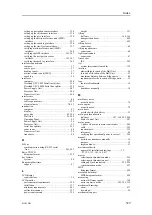
IEC....................................................... 229
system interconnection cables........................ 195
athwartships location of the Hull Unit ................ 58
fore and aft location of the Hull Unit ................. 57
maximum distance between bridge units ............. 60
requirements for the location of bridge units......... 59
registered trademark..................................... 16
transducer manually ..................................... 18
M
acoustic noise............................................. 78
acoustic noise............................................. 78
provided with the delivery.............................. 32
main parts identification
hull unit ............................... 147, 164, 285–286
Motor Control Unit .................................... 287
3–phase AC mains to motor control unit ........... 249
cable ..................................................... 229
requirements ............................................ 395
tolerances ................................................. 44
verifying that operational power is correct ......... 298
hoist/lower transducer manually ....................... 18
purpose .................................................... 15
target audience ........................................... 15
maritime authority
approval of installation drawings ............. 15,
selecting synchronization mode...................... 226
selecting synchronization port ....................... 225
setting up synchronization ...................... 225–226
synchronization mode ................................. 223
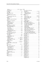
datagram format........................................ 420
MDS datagram format ................................ 420
noise at different speeds .............................. 358
noise in passive mode ..................... 301, 303, 355
about ..................................................... 437
download.................................................. 54
mechanical support
Index
Summary of Contents for SC90
Page 2: ......
Page 16: ...14 419050 B Simrad SC90 ...
Page 219: ...419050 B 217 Øverland UPC 3005 Dimensions Cable layout and interconnections ...
Page 223: ...419050 B 221 Øverland UPC 5000P Dimensions Cable layout and interconnections ...
Page 438: ...436 419050 B 427177 Transducer dock dimensions page 494 Simrad SC90 Installation Manual ...
Page 441: ...419050 B 439 Drawing file ...
Page 442: ...440 419050 B Simrad SC90 Installation Manual ...
Page 445: ...419050 B 443 Drawing file ...
Page 452: ...450 419050 B Simrad SC90 Installation Manual ...
Page 455: ...419050 B 453 Drawing file ...
Page 458: ...456 419050 B Simrad SC90 Installation Manual ...
Page 463: ...419050 B 461 Drawing file ...
Page 468: ...466 419050 B Simrad SC90 Installation Manual ...
Page 469: ...419050 B 467 Related topics Installing the optional gate valve DN350 page 84 Drawing file ...
Page 471: ...419050 B 469 Drawing file ...
Page 473: ...419050 B 471 214043 Gate valve installation DN350 Drawing file ...
Page 475: ...419050 B 473 422915 Gate valve installation DN350 Drawing file ...
Page 477: ...419050 B 475 083045 Gate valve installation DN500 Drawing file ...
Page 479: ...419050 B 477 33414 Gate valve dimensions DN350 Drawing file ...
Page 480: ...478 419050 B Simrad SC90 Installation Manual ...
Page 481: ...419050 B 479 Related topics Installing the optional gate valve DN350 page 84 Drawing file ...
Page 482: ...480 419050 B 33473 Gate valve dimensions DN350 Simrad SC90 Installation Manual ...
Page 483: ...419050 B 481 Related topics Installing the optional gate valve DN350 page 84 Drawing file ...
Page 484: ...482 419050 B 33498 Gate valve dimensions DN500 Simrad SC90 Installation Manual ...
Page 485: ...419050 B 483 Drawing file ...
Page 487: ...419050 B 485 37357 Gate valve dimensions DN500 Drawing file ...
Page 488: ...486 419050 B Simrad SC90 Installation Manual ...
Page 489: ...419050 B 487 Related topics Installing the optional gate valve DN500 page 103 Drawing file ...
Page 491: ...419050 B 489 Drawing file ...
Page 494: ...492 419050 B Simrad SC90 Installation Manual ...
Page 495: ...419050 B 493 Related topics Installing the optional gate valve DN350 page 84 Drawing file ...
Page 497: ...419050 B 495 Drawing file ...
Page 542: ... 2018Kongsberg Maritime ISBN xxx ...
Page 543: ......
Page 544: ...Simrad SC90 Fish finding sonar Installation Manual ...


