419050/B
531
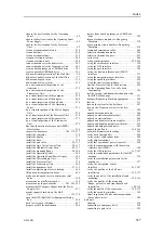
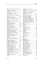
about acoustic noise ..................................... 76
ambient noise............................................. 80
cavitation.................................................. 79
contributing factors ...................................... 76
electrical noise ...................................... 78, 81
flow noise ................................................. 79
interference ............................................... 80
machinery noise.......................................... 78
making a noise/speed curve to determine vessel
noise.................................................... 358
measuring ............................. 301, 303, 355, 358
propeller noise............................................ 78
rattle noise ................................................ 80
reverberation.............................................. 81
self noise .................................................. 78
Hull Unit location........................................ 58
noise sources ................................................ 76
general requirements .................................... 45
noise suppressor
Ethernet cable .................................... 247–248
making .................................................. 358
synchronization mode ................................. 223
before you power up..................................... 17
important reminders ..................................... 17
support if something breaks down..................... 18
when the system not in use ............................. 18
when you are docking your vessel..................... 18
when you wish to switch off ........................... 18
O
support .................................................... 47
turn....................................................... 311
information ............................................... 16
secondary ................................................. 39
choosing the best location .............................. 62
compass safe distance ............................. 62, 401
environmental requirements.......................... 399
functional test .......................................... 345
installing ................................................ 180
introduction ............................................... 25
outline dimensions..................................... 397
outline dimensions drawing .......................... 445
overview .................................................. 25
power requirements.................................... 395
purpose .................................................... 25
visual inspection ....................................... 271
weight ................................................... 397
choosing the best location .............................. 62
environmental requirements.......................... 399
installing ................................................ 182
power requirements.................................... 395
computer ................................................ 395
display ................................................... 395
Processor Unit.......................................... 395
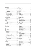
verify .................................................... 298
gate valve ................................................. 39
motion reference unit (MRU) .......................... 41
secondary operating panel .............................. 39
serial line splitter......................................... 41
not provided with the delivery ......................... 38
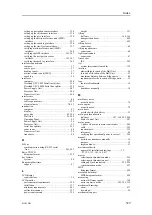
hull unit ................................................... 69
about ..................................................... 437
computer ................................................ 397
display ................................................... 397
download.................................................. 54
gate valve outline dimensions
drawing .............................. 477, 480, 482, 485
hull unit ................................................. 398
Operating Panel ........................................ 397
Power Supply Unit .................................... 398
Processor Unit.......................................... 397
specifications ........................................... 397
transceiver .............................................. 397
Transceiver Unit ....................................... 397
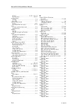
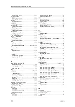
outline dimensions drawing
blind panel ........................................ 463–464
computer ................................................ 438
Hull Unit .......................................... 449, 452
installation trunk ........................... 455, 458, 460
mounting flange .................................. 465, 468
Operating Panel ........................................ 445
Øverland UPC-3005 Serial line splitter............. 217
Øverland UPC-5000P Serial line splitter ........... 221
Power Supply Unit .................................... 447
Processor Unit.......................................... 438
Transceiver Unit ....................................... 442
transducer dock ............................ 488, 491, 494
measuring the DC output voltages from the
Power Supply Unit ................................... 357
connections ............................................. 216
description .............................................. 214
outline dimensions drawing .......................... 217
technical specifications................................ 215
connections ............................................. 220
description .............................................. 218
outline dimensions drawing .......................... 221
technical specifications................................ 219
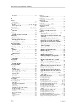
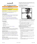
computer .................................................. 23
display ..................................................... 22
gate valve ........................................... 85, 104
Hull Unit ............................................ 26, 282
installation tasks ......................................... 51
Operating Panel .......................................... 25
Power Supply Unit ...................................... 26
Processor Unit............................................ 23
serial line splitters...................................... 213
sonar room ................................................ 64
Transceiver Unit ......................................... 24
Index
Summary of Contents for SC90
Page 2: ......
Page 16: ...14 419050 B Simrad SC90 ...
Page 219: ...419050 B 217 Øverland UPC 3005 Dimensions Cable layout and interconnections ...
Page 223: ...419050 B 221 Øverland UPC 5000P Dimensions Cable layout and interconnections ...
Page 438: ...436 419050 B 427177 Transducer dock dimensions page 494 Simrad SC90 Installation Manual ...
Page 441: ...419050 B 439 Drawing file ...
Page 442: ...440 419050 B Simrad SC90 Installation Manual ...
Page 445: ...419050 B 443 Drawing file ...
Page 452: ...450 419050 B Simrad SC90 Installation Manual ...
Page 455: ...419050 B 453 Drawing file ...
Page 458: ...456 419050 B Simrad SC90 Installation Manual ...
Page 463: ...419050 B 461 Drawing file ...
Page 468: ...466 419050 B Simrad SC90 Installation Manual ...
Page 469: ...419050 B 467 Related topics Installing the optional gate valve DN350 page 84 Drawing file ...
Page 471: ...419050 B 469 Drawing file ...
Page 473: ...419050 B 471 214043 Gate valve installation DN350 Drawing file ...
Page 475: ...419050 B 473 422915 Gate valve installation DN350 Drawing file ...
Page 477: ...419050 B 475 083045 Gate valve installation DN500 Drawing file ...
Page 479: ...419050 B 477 33414 Gate valve dimensions DN350 Drawing file ...
Page 480: ...478 419050 B Simrad SC90 Installation Manual ...
Page 481: ...419050 B 479 Related topics Installing the optional gate valve DN350 page 84 Drawing file ...
Page 482: ...480 419050 B 33473 Gate valve dimensions DN350 Simrad SC90 Installation Manual ...
Page 483: ...419050 B 481 Related topics Installing the optional gate valve DN350 page 84 Drawing file ...
Page 484: ...482 419050 B 33498 Gate valve dimensions DN500 Simrad SC90 Installation Manual ...
Page 485: ...419050 B 483 Drawing file ...
Page 487: ...419050 B 485 37357 Gate valve dimensions DN500 Drawing file ...
Page 488: ...486 419050 B Simrad SC90 Installation Manual ...
Page 489: ...419050 B 487 Related topics Installing the optional gate valve DN500 page 103 Drawing file ...
Page 491: ...419050 B 489 Drawing file ...
Page 494: ...492 419050 B Simrad SC90 Installation Manual ...
Page 495: ...419050 B 493 Related topics Installing the optional gate valve DN350 page 84 Drawing file ...
Page 497: ...419050 B 495 Drawing file ...
Page 542: ... 2018Kongsberg Maritime ISBN xxx ...
Page 543: ......
Page 544: ...Simrad SC90 Fish finding sonar Installation Manual ...


