419050/B
9
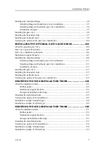
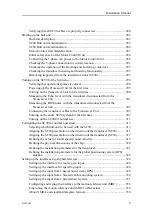
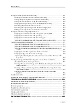
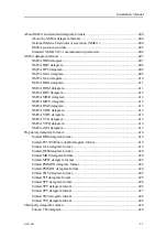
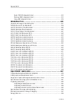
Verifying that all SC90 cables are properly connected ........................................280
Hull unit description .............................................................................................282
SC90 Hull unit familiarization .............................................................................285
SC94 Hull unit familiarization .............................................................................286
Motor Control Unit familiarization ......................................................................287
Initial safety check of the Motor Control Unit .....................................................288
Connecting the 3-phase AC power to the Motor Control Unit ............................289
Checking the 3-phase connection for correct rotation..........................................291
Checking the operation of the Hoisting and Lowering contactors .......................293
Checking the transducer lowering and hoisting functionality..............................295
Removing trapped air from the installation trunk (SC90)....................................297
Verifying that operational power is correct ..........................................................298
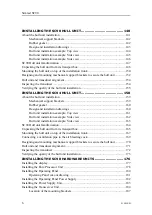
Powering up the Processor Unit for the first time ................................................299
Turning on the Transceiver Unit for the first time................................................300
Measuring the Echo level with the transducer disconnected from the
Measuring the BITE noise with the transducer disconnected from the
Connecting the transducer cables to the Transceiver Unit ...................................305
Turning on the entire SC90 system for the first time ...........................................307
Turning on the SC90 for normal use .................................................................... 311
Selecting which hull unit to be used with the SC90.............................................313
Aligning the SC90 presentation to the direction of the transducer (SC90) ...........315
Aligning the SC90 presentation to the direction of the transducer (SC94) ...........317
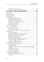
Defining the value for sound speed (sound velocity) ...........................................319
Defining the physical dimensions of the ship.......................................................320
Defining the installation parameters for the transducer........................................321
Defining the installation parameters for the global positioning system (GPS)
Setting up the interface for course gyro input ......................................................324
Setting up the interface for speed log input..........................................................326
Setting up the input from a navigation system (GPS) ..........................................328
Setting up the input from a Simrad catch monitoring system ..............................330
Setting up the input from a Simrad trawl system .................................................331
Configuring and testing the interface to the motion reference unit (MRU) ...........333
Fine tuning the motion reference unit (MRU) offset values ................................336
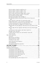
About NMEA and standard datagram formats.....................................................338
Installation Manual
Summary of Contents for SC90
Page 2: ......
Page 16: ...14 419050 B Simrad SC90 ...
Page 219: ...419050 B 217 Øverland UPC 3005 Dimensions Cable layout and interconnections ...
Page 223: ...419050 B 221 Øverland UPC 5000P Dimensions Cable layout and interconnections ...
Page 438: ...436 419050 B 427177 Transducer dock dimensions page 494 Simrad SC90 Installation Manual ...
Page 441: ...419050 B 439 Drawing file ...
Page 442: ...440 419050 B Simrad SC90 Installation Manual ...
Page 445: ...419050 B 443 Drawing file ...
Page 452: ...450 419050 B Simrad SC90 Installation Manual ...
Page 455: ...419050 B 453 Drawing file ...
Page 458: ...456 419050 B Simrad SC90 Installation Manual ...
Page 463: ...419050 B 461 Drawing file ...
Page 468: ...466 419050 B Simrad SC90 Installation Manual ...
Page 469: ...419050 B 467 Related topics Installing the optional gate valve DN350 page 84 Drawing file ...
Page 471: ...419050 B 469 Drawing file ...
Page 473: ...419050 B 471 214043 Gate valve installation DN350 Drawing file ...
Page 475: ...419050 B 473 422915 Gate valve installation DN350 Drawing file ...
Page 477: ...419050 B 475 083045 Gate valve installation DN500 Drawing file ...
Page 479: ...419050 B 477 33414 Gate valve dimensions DN350 Drawing file ...
Page 480: ...478 419050 B Simrad SC90 Installation Manual ...
Page 481: ...419050 B 479 Related topics Installing the optional gate valve DN350 page 84 Drawing file ...
Page 482: ...480 419050 B 33473 Gate valve dimensions DN350 Simrad SC90 Installation Manual ...
Page 483: ...419050 B 481 Related topics Installing the optional gate valve DN350 page 84 Drawing file ...
Page 484: ...482 419050 B 33498 Gate valve dimensions DN500 Simrad SC90 Installation Manual ...
Page 485: ...419050 B 483 Drawing file ...
Page 487: ...419050 B 485 37357 Gate valve dimensions DN500 Drawing file ...
Page 488: ...486 419050 B Simrad SC90 Installation Manual ...
Page 489: ...419050 B 487 Related topics Installing the optional gate valve DN500 page 103 Drawing file ...
Page 491: ...419050 B 489 Drawing file ...
Page 494: ...492 419050 B Simrad SC90 Installation Manual ...
Page 495: ...419050 B 493 Related topics Installing the optional gate valve DN350 page 84 Drawing file ...
Page 497: ...419050 B 495 Drawing file ...
Page 542: ... 2018Kongsberg Maritime ISBN xxx ...
Page 543: ......
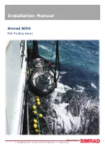
Page 544: ...Simrad SC90 Fish finding sonar Installation Manual ...

