419050/B
289
Connecting the 3-phase AC power to the Motor Control Unit
The electric hoisting motor on the hull unit requires 3-phase AC power for operation.
The AC power is connected to terminal block E301 inside the Motor Control Unit.
Prerequisites
• The SC90 is turned off.
• The circuit breaker for the 3-phase
AC power is disengaged.
• All cable connections are made.
You must be equipped with a
standard set of tools. This tool set
must comprise the normal tools for
electronic and electromechanical
tasks. This includes different
screwdriver types, pliers, spanners,
a cable stripper, a soldering iron etc.
Each tool must be provided in various
sizes. We recommend that all tools
are demagnetized to protect your
equipment. The following specific
instrument is required for this task:
• Multimeter
Context
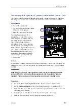
Terminal block
E301
is located at the bottom of the Motor Control Unit. The three AC
mains power cables, as well as ground, are connected from the ship’s circuit breakers
to
E301
.
WARNING
High voltages are used. This equipment must only be serviced by qualified
personnel familiar with high-voltage equipment and the potential hazards
involved. Failure to observe this precaution could result in bodily injury.
Procedure
1
Locate the
Motor Protecting Switch
(S301). Set the switch to position
OFF
.
2
Locate
Hoist/Lower Switch
(S302). Check that the switch is in position
STOP
.
3
Make sure that each cable has been installed as specified in the
Cable layout and
interconnections
chapter.
4
To apply power, close the circuit breaker for the 3-phase AC voltage.
5
Measure the 3-phase AC mains voltage on terminal block E301.
Summary of Contents for SC90
Page 2: ......
Page 16: ...14 419050 B Simrad SC90 ...
Page 219: ...419050 B 217 Øverland UPC 3005 Dimensions Cable layout and interconnections ...
Page 223: ...419050 B 221 Øverland UPC 5000P Dimensions Cable layout and interconnections ...
Page 438: ...436 419050 B 427177 Transducer dock dimensions page 494 Simrad SC90 Installation Manual ...
Page 441: ...419050 B 439 Drawing file ...
Page 442: ...440 419050 B Simrad SC90 Installation Manual ...
Page 445: ...419050 B 443 Drawing file ...
Page 452: ...450 419050 B Simrad SC90 Installation Manual ...
Page 455: ...419050 B 453 Drawing file ...
Page 458: ...456 419050 B Simrad SC90 Installation Manual ...
Page 463: ...419050 B 461 Drawing file ...
Page 468: ...466 419050 B Simrad SC90 Installation Manual ...
Page 469: ...419050 B 467 Related topics Installing the optional gate valve DN350 page 84 Drawing file ...
Page 471: ...419050 B 469 Drawing file ...
Page 473: ...419050 B 471 214043 Gate valve installation DN350 Drawing file ...
Page 475: ...419050 B 473 422915 Gate valve installation DN350 Drawing file ...
Page 477: ...419050 B 475 083045 Gate valve installation DN500 Drawing file ...
Page 479: ...419050 B 477 33414 Gate valve dimensions DN350 Drawing file ...
Page 480: ...478 419050 B Simrad SC90 Installation Manual ...
Page 481: ...419050 B 479 Related topics Installing the optional gate valve DN350 page 84 Drawing file ...
Page 482: ...480 419050 B 33473 Gate valve dimensions DN350 Simrad SC90 Installation Manual ...
Page 483: ...419050 B 481 Related topics Installing the optional gate valve DN350 page 84 Drawing file ...
Page 484: ...482 419050 B 33498 Gate valve dimensions DN500 Simrad SC90 Installation Manual ...
Page 485: ...419050 B 483 Drawing file ...
Page 487: ...419050 B 485 37357 Gate valve dimensions DN500 Drawing file ...
Page 488: ...486 419050 B Simrad SC90 Installation Manual ...
Page 489: ...419050 B 487 Related topics Installing the optional gate valve DN500 page 103 Drawing file ...
Page 491: ...419050 B 489 Drawing file ...
Page 494: ...492 419050 B Simrad SC90 Installation Manual ...
Page 495: ...419050 B 493 Related topics Installing the optional gate valve DN350 page 84 Drawing file ...
Page 497: ...419050 B 495 Drawing file ...
Page 542: ... 2018Kongsberg Maritime ISBN xxx ...
Page 543: ......
Page 544: ...Simrad SC90 Fish finding sonar Installation Manual ...


