419050/B
315
Aligning the SC90 presentation to the direction of the
transducer (SC90)
When the installation trunk is mounted, it may not be positioned with the mounting holes
in the right directions. When the hull unit is placed on the trunk, the "forward" mark
on the transducer shaft sleeve - and thus also the transducer - are both misaligned. To
obtain accurate SC90 presentations, this must be adjusted. Note that this task is only
relevant for the SC90 Hull Unit.
Prerequisites
The SC90 is installed as specified
in this manual.
• The SC90 is turned on, and it is
working normally.
• The SC90 is in
Normal
mode, but
TX Power
is set to
Off
to prevent
transmission.
• The transducer is retracted to its
upper position.
• The vessel is berthed or at sea.
Neither tools nor instruments are
required.
Caution
You must never set the SC90 to
"ping" unless the transducer is
submerged in water. The transducer
may be damaged if it transmits in
open air.
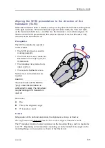
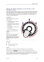
Illustration:
A
Bow
B
This is the alignment angle
C
0
°
transducer mark
Context
Independent of the hull unit orientation, the alignment is always defined as:
The angle measured clockwise from the bow to the 0 degrees transducer mark.
The 0° transducer mark is located outermost on the mounting flange, and it is marked as
a red "0". Depending on the transducer mounting, it can be located at any angle on the
mounting flange, not necessarily as shown in the illustration.
Summary of Contents for SC90
Page 2: ......
Page 16: ...14 419050 B Simrad SC90 ...
Page 219: ...419050 B 217 Øverland UPC 3005 Dimensions Cable layout and interconnections ...
Page 223: ...419050 B 221 Øverland UPC 5000P Dimensions Cable layout and interconnections ...
Page 438: ...436 419050 B 427177 Transducer dock dimensions page 494 Simrad SC90 Installation Manual ...
Page 441: ...419050 B 439 Drawing file ...
Page 442: ...440 419050 B Simrad SC90 Installation Manual ...
Page 445: ...419050 B 443 Drawing file ...
Page 452: ...450 419050 B Simrad SC90 Installation Manual ...
Page 455: ...419050 B 453 Drawing file ...
Page 458: ...456 419050 B Simrad SC90 Installation Manual ...
Page 463: ...419050 B 461 Drawing file ...
Page 468: ...466 419050 B Simrad SC90 Installation Manual ...
Page 469: ...419050 B 467 Related topics Installing the optional gate valve DN350 page 84 Drawing file ...
Page 471: ...419050 B 469 Drawing file ...
Page 473: ...419050 B 471 214043 Gate valve installation DN350 Drawing file ...
Page 475: ...419050 B 473 422915 Gate valve installation DN350 Drawing file ...
Page 477: ...419050 B 475 083045 Gate valve installation DN500 Drawing file ...
Page 479: ...419050 B 477 33414 Gate valve dimensions DN350 Drawing file ...
Page 480: ...478 419050 B Simrad SC90 Installation Manual ...
Page 481: ...419050 B 479 Related topics Installing the optional gate valve DN350 page 84 Drawing file ...
Page 482: ...480 419050 B 33473 Gate valve dimensions DN350 Simrad SC90 Installation Manual ...
Page 483: ...419050 B 481 Related topics Installing the optional gate valve DN350 page 84 Drawing file ...
Page 484: ...482 419050 B 33498 Gate valve dimensions DN500 Simrad SC90 Installation Manual ...
Page 485: ...419050 B 483 Drawing file ...
Page 487: ...419050 B 485 37357 Gate valve dimensions DN500 Drawing file ...
Page 488: ...486 419050 B Simrad SC90 Installation Manual ...
Page 489: ...419050 B 487 Related topics Installing the optional gate valve DN500 page 103 Drawing file ...
Page 491: ...419050 B 489 Drawing file ...
Page 494: ...492 419050 B Simrad SC90 Installation Manual ...
Page 495: ...419050 B 493 Related topics Installing the optional gate valve DN350 page 84 Drawing file ...
Page 497: ...419050 B 495 Drawing file ...
Page 542: ... 2018Kongsberg Maritime ISBN xxx ...
Page 543: ......
Page 544: ...Simrad SC90 Fish finding sonar Installation Manual ...


