250
419050/B
Emergency hoist connections
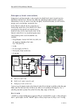
Emergency hoist functionality is provided by the Hull Unit Control circuit board in
the Motor Control Unit. We does not offer any optional products or kits to put this
functionality to use. In order to use the emergency hoist functionality you will need to
design your own interface and switch box.
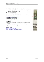
In the Motor Control Unit, the connection as
made using socket
P9
on the Hull Unit Control
circuit board. The Hull Unit Control circuit
board is located in the lower right corner of the
Motor Control Unit. It is mounted upside down.
The following items and consumables are
required.
• Plug Phoenix Contact MCVW1.5/4-STF-3.81
(Kongsberg Maritime Part num-
ber: 370–097775)
• Cable
• Power supply (24 VDC)
• Emergency hoist switch box
• Grommet
A
Motor Control Unit
B
Hull Unit Control circuit board
C
Emergency hoist switch box
You may need to make a hole in the Motor Control Unit cabinet to pull the cable through.
Make sure that the hole does not have any effect on its splash proof integrity. Use a
suitable grommet to protect the cable from the sharp edges of the hole.
How it works
+24 VDC is connected through a suggested "Hoist" switch (SW1) to pin 3. This will open
the U7 optocoupler, and the "Inhibit" input on the microprocessor will go "low" forcing
Simrad SC90 Installation Manual
Summary of Contents for SC90
Page 2: ......
Page 16: ...14 419050 B Simrad SC90 ...
Page 219: ...419050 B 217 Øverland UPC 3005 Dimensions Cable layout and interconnections ...
Page 223: ...419050 B 221 Øverland UPC 5000P Dimensions Cable layout and interconnections ...
Page 438: ...436 419050 B 427177 Transducer dock dimensions page 494 Simrad SC90 Installation Manual ...
Page 441: ...419050 B 439 Drawing file ...
Page 442: ...440 419050 B Simrad SC90 Installation Manual ...
Page 445: ...419050 B 443 Drawing file ...
Page 452: ...450 419050 B Simrad SC90 Installation Manual ...
Page 455: ...419050 B 453 Drawing file ...
Page 458: ...456 419050 B Simrad SC90 Installation Manual ...
Page 463: ...419050 B 461 Drawing file ...
Page 468: ...466 419050 B Simrad SC90 Installation Manual ...
Page 469: ...419050 B 467 Related topics Installing the optional gate valve DN350 page 84 Drawing file ...
Page 471: ...419050 B 469 Drawing file ...
Page 473: ...419050 B 471 214043 Gate valve installation DN350 Drawing file ...
Page 475: ...419050 B 473 422915 Gate valve installation DN350 Drawing file ...
Page 477: ...419050 B 475 083045 Gate valve installation DN500 Drawing file ...
Page 479: ...419050 B 477 33414 Gate valve dimensions DN350 Drawing file ...
Page 480: ...478 419050 B Simrad SC90 Installation Manual ...
Page 481: ...419050 B 479 Related topics Installing the optional gate valve DN350 page 84 Drawing file ...
Page 482: ...480 419050 B 33473 Gate valve dimensions DN350 Simrad SC90 Installation Manual ...
Page 483: ...419050 B 481 Related topics Installing the optional gate valve DN350 page 84 Drawing file ...
Page 484: ...482 419050 B 33498 Gate valve dimensions DN500 Simrad SC90 Installation Manual ...
Page 485: ...419050 B 483 Drawing file ...
Page 487: ...419050 B 485 37357 Gate valve dimensions DN500 Drawing file ...
Page 488: ...486 419050 B Simrad SC90 Installation Manual ...
Page 489: ...419050 B 487 Related topics Installing the optional gate valve DN500 page 103 Drawing file ...
Page 491: ...419050 B 489 Drawing file ...
Page 494: ...492 419050 B Simrad SC90 Installation Manual ...
Page 495: ...419050 B 493 Related topics Installing the optional gate valve DN350 page 84 Drawing file ...
Page 497: ...419050 B 495 Drawing file ...
Page 542: ... 2018Kongsberg Maritime ISBN xxx ...
Page 543: ......
Page 544: ...Simrad SC90 Fish finding sonar Installation Manual ...

