419050/B
223
Synchronization modes
The purpose of the synchronization modes are to set up the SC90 to operate alone, or as
a "master" or "slave" in a synchronized system.
Whenever more than one hydroacoustic system is
installed on a vessel, interference may occur. To avoid
this, you have these options:
• The systems are all connected to a common
synchronization system.
• One of the acoustic systems is set up as "master",
and controls the transmissions on the other systems.
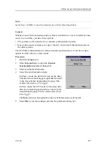
The SC90 offers functionality for remote transmit
synchronisation. It can be set up to operate in either
Master
or
Slave
mode.
The following synchronization modes are available.
•
None
Synchronization is switched off.This synchronization mode is used if the SC90 is
working by itself, and with no synchronization required. This is the default setting.
The SC90 operates using its internal ping interval parameters, independent of any
trigger signals arriving at the synchronization port.
The
Delay
setting is not applicable when synchronization is switched off.
•
Master
The
Master
mode is used if the SC90 shall act as the "controlling" unit in a
synchronized system. The peripheral hydroacoustic system(s) are only permitted to
transmit when enabled by the SC90. When the
Master
mode is chosen, the SC90
will run using its internal ping interval parameters, and send trigger signals to the
peripheral system(s).
•
Slave
The
Slave
mode is used if the SC90 shall transmit only when permitted by a peripheral
system. When the
Slave
mode is chosen, the SC90 does not transmit ("ping") unless
an external trigger appears on the chosen synchronization port. The peripheral system
may be any other hydroacoustic product (for example an echo sounder or sonar), or
even a dedicated synchronisation system.
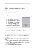
Note
To select synchronization mode, use the
External Synchronization
parameter dialog
box on the
Setup
menu.
To choose which communication port to use, select
I/O Setup
on the
Installation
menu.
On the
I/O Setup
menu, select
External Sync
to open the
Sync Port Configuration
parameter dialog.
Summary of Contents for SC90
Page 2: ......
Page 16: ...14 419050 B Simrad SC90 ...
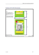
Page 219: ...419050 B 217 Øverland UPC 3005 Dimensions Cable layout and interconnections ...
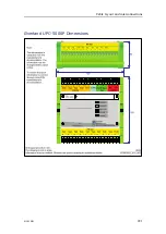
Page 223: ...419050 B 221 Øverland UPC 5000P Dimensions Cable layout and interconnections ...
Page 438: ...436 419050 B 427177 Transducer dock dimensions page 494 Simrad SC90 Installation Manual ...
Page 441: ...419050 B 439 Drawing file ...
Page 442: ...440 419050 B Simrad SC90 Installation Manual ...
Page 445: ...419050 B 443 Drawing file ...
Page 452: ...450 419050 B Simrad SC90 Installation Manual ...
Page 455: ...419050 B 453 Drawing file ...
Page 458: ...456 419050 B Simrad SC90 Installation Manual ...
Page 463: ...419050 B 461 Drawing file ...
Page 468: ...466 419050 B Simrad SC90 Installation Manual ...
Page 469: ...419050 B 467 Related topics Installing the optional gate valve DN350 page 84 Drawing file ...
Page 471: ...419050 B 469 Drawing file ...
Page 473: ...419050 B 471 214043 Gate valve installation DN350 Drawing file ...
Page 475: ...419050 B 473 422915 Gate valve installation DN350 Drawing file ...
Page 477: ...419050 B 475 083045 Gate valve installation DN500 Drawing file ...
Page 479: ...419050 B 477 33414 Gate valve dimensions DN350 Drawing file ...
Page 480: ...478 419050 B Simrad SC90 Installation Manual ...
Page 481: ...419050 B 479 Related topics Installing the optional gate valve DN350 page 84 Drawing file ...
Page 482: ...480 419050 B 33473 Gate valve dimensions DN350 Simrad SC90 Installation Manual ...
Page 483: ...419050 B 481 Related topics Installing the optional gate valve DN350 page 84 Drawing file ...
Page 484: ...482 419050 B 33498 Gate valve dimensions DN500 Simrad SC90 Installation Manual ...
Page 485: ...419050 B 483 Drawing file ...
Page 487: ...419050 B 485 37357 Gate valve dimensions DN500 Drawing file ...
Page 488: ...486 419050 B Simrad SC90 Installation Manual ...
Page 489: ...419050 B 487 Related topics Installing the optional gate valve DN500 page 103 Drawing file ...
Page 491: ...419050 B 489 Drawing file ...
Page 494: ...492 419050 B Simrad SC90 Installation Manual ...
Page 495: ...419050 B 493 Related topics Installing the optional gate valve DN350 page 84 Drawing file ...
Page 497: ...419050 B 495 Drawing file ...
Page 542: ... 2018Kongsberg Maritime ISBN xxx ...
Page 543: ......
Page 544: ...Simrad SC90 Fish finding sonar Installation Manual ...


