2-24
CQO:1010PVXFM-3
Section 2
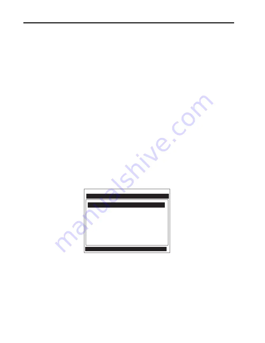
Note on the screen above that there are two columns, a left-hand and a right-hand side. The first left-
hand item, [Meter Type], is highlighted (reversed). [Meter Type] allows you to choose a configuration
from the right-hand column list (on Single Channel models, there is only a single channel)
.
The next
left-hand selection is Meter Facilities. Use this menu to set global options and controls.
Siemens Site [1] Channel 1
Select Meter Type
Meter Type 2 Channel Flow
Meter Facilities
Liquid Class
The datalogger contains data that has its fields separated by commas. By using the file extension “.csv”
(comma separated values) suggested earlier, the data will import directly into MS Excel without any
further modification. For the waveshape data, the fields are separated by spaces, therefore, it is best to
save those files as “.txt”, then use the MS Excel Import Wizard to select “Space Delimiters” for importation
of the data.
Site data is downloaded in plain text and can be imported directly into MS Word.
2.7.5 DATA ENTRY USING THE RS-232 INTERFACE
The following is a step-by-step example of how to enter data for a Single-Channel FUH1010PVX flow
computer using the RS-232 interface and a communications program. Again, don’t let the size of the
Installation Menu intimidate you. Most menu cells contain default parameters. You need only access the
menu cells that control a needed parameter, such as the pipe outer diameter.
Accessing and Leaving the Menu
z
Make sure the Menu Lockout Switch is in the correct position. Connect the serial interface cable
between the flow computer and your laptop computer.
z
Run HyperTerminal (or your choice of communication program) using settings explained previously.
z
In Command Mode, type [menu 1000]; press <ENT> to select the top level of the Installation Menu.
NOTE: Type <Menu> to enter Installation Menu. After programming is complete, repeated <Left
Arrow> key will access the Flow Display. Key <Enter> from Flow Display to re-enter menu.
Key <Ctrl L> to exit menu.
Summary of Contents for SITRANS FUH1010PVDX
Page 2: ......
Page 4: ......
Page 8: ......
Page 12: ......
Page 20: ......
Page 24: ......
Page 32: ......
Page 184: ......
Page 204: ......
Page 206: ......
Page 208: ......
Page 216: ......
Page 219: ...21614 C 1010X 7 CAUTION ...
Page 222: ...STANDARD UPRIGHT INSTALLATION 21614 C 1010X 8 ...
Page 223: ...21614 C 1010DX 7 CAUTION ...
Page 227: ...21614 C 1010DX 8 STANDARD UPRIGHT INSTALLATION ...
Page 228: ......
Page 229: ......
Page 230: ......
Page 231: ......
Page 232: ......
Page 233: ......
Page 234: ...1011HNFS 7 21614 C ...
Page 235: ...1011HNFS 7 C 21614 ...
Page 237: ......
Page 241: ...1011NFPS 7 C 21614 REFLECT MODE OPERATION DIRECT MODE OPERATION AUXILIARY VIEW ...
Page 242: ...1011NFPS 8 21614 C ...
Page 243: ......
Page 249: ......
Page 250: ......
Page 251: ...1012TB 8 INSTALLATION OUTLINE 1011 SERIES TEST BLOCK 21614 C ...
Page 254: ...1012TN 8 OUTLINE DIMENSIONS REFLECT MODE DIRECT MODE 1012TN SERIES 21614 C MOUNTING TRACK ...
Page 257: ...1012TNH 8 OUTLINE DIMENSIONS REFLECT MODE DIRECT MODE 1012TNH SERIES 21614 C MOUNTING TRACK ...
Page 258: ...1012F DB 7 21614 C ...
Page 259: ......
Page 260: ......
Page 261: ......
Page 262: ...21614 C OUTLINE DIMENSIONS WELD SEAL TYPE 1013WS 8 ENCLOSURES ...
Page 263: ......
Page 264: ......
Page 265: ......
Page 266: ......
Page 267: ......
Page 269: ...21614 C TEMPERATURE SENSOR DEDICATED NEMA 4 OUTLINE DIMENSIONS 991TN 8 5 4 3 2 1 ...
Page 270: ......
Page 271: ......
Page 273: ......
Page 274: ......
Page 275: ......
Page 276: ......
Page 286: ......
Page 304: ......
Page 307: ......


