


1-5
CQO:1010PVXFM-3
Section 1
( )
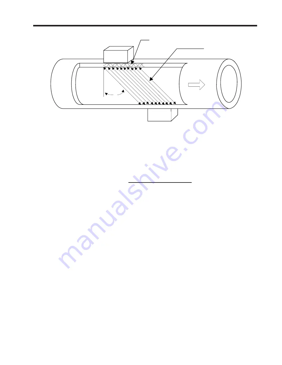
Wide Beam Transmission
As shown in the figure above, an ultrasonic transducer induces an axial sonic beam within the wall of the
pipe. These vibrations spread along the pipe wall and then enter the liquid in the form of a Wide Beam
wave front traveling at an angle to the main pipe axis. The wide beam “rains” over the receiving trans-
ducer. The wide coverage of the receiver is necessary because the angle of the sonic beam is related to
the liquid’s sonic propagation velocity by Snell’s Law.
According to this formula, we can state that,
as the liquid sonic propagation velocity changes so will
the angle between the sonic beam and the flow stream
.
θ
Upstream
transducer
Downstream
transducer
Beam Angle
FLOW
Wide Beam™
Axial Beam Injection
into pipe wall
Sonic Wave front
Therefore, a significant liquid sonic velocity shift could deflect a “narrow” beam transmission away from
the receiving transducer entirely. The upstream vs. downstream transit-time difference will also be af-
fected by the changing (or refracting) beam angle. This makes it necessary for clamp-on systems to
continuously compute this angle, since it is subject to varying degrees of refraction. The flow computer
derives the angle by knowing the fixed position of the transducers, the dimensions of the pipe and the
measured transit-time. Therefore, the flow computer computes the beam angle relative to the axis of the
pipe.
Flow Calibration Factor
Normally, the flow stream is in line with the axis of the pipe. On this basis, the calibration factor of a
Clamp-on ultrasonic flowmeter is proportional to the cosine of the beam angle relative to the pipe axis.
However, this reveals that if the angle of flow stream is
not
in line with the pipe axis, the flow calibration
factor could be compromised. This most often occurs when the transducer mounting location is within
close proximity of a bend or other pipe obstruction. This is why we recommend that whenever possible
you mount clamp-on transducers on the longest available straight run of pipe and also use Reflect Mode
mounting (see next page).
Beam Angle = Arc Sine
Liquid Sonic Propagation Velocity
Transducer Phase Velocity
Summary of Contents for SITRANS FUH1010PVDX
Page 2: ......
Page 4: ......
Page 8: ......
Page 12: ......
Page 20: ......
Page 24: ......
Page 32: ......
Page 184: ......
Page 204: ......
Page 206: ......
Page 208: ......
Page 216: ......
Page 219: ...21614 C 1010X 7 CAUTION ...
Page 222: ...STANDARD UPRIGHT INSTALLATION 21614 C 1010X 8 ...
Page 223: ...21614 C 1010DX 7 CAUTION ...
Page 227: ...21614 C 1010DX 8 STANDARD UPRIGHT INSTALLATION ...
Page 228: ......
Page 229: ......
Page 230: ......
Page 231: ......
Page 232: ......
Page 233: ......
Page 234: ...1011HNFS 7 21614 C ...
Page 235: ...1011HNFS 7 C 21614 ...
Page 237: ......
Page 241: ...1011NFPS 7 C 21614 REFLECT MODE OPERATION DIRECT MODE OPERATION AUXILIARY VIEW ...
Page 242: ...1011NFPS 8 21614 C ...
Page 243: ......
Page 249: ......
Page 250: ......
Page 251: ...1012TB 8 INSTALLATION OUTLINE 1011 SERIES TEST BLOCK 21614 C ...
Page 254: ...1012TN 8 OUTLINE DIMENSIONS REFLECT MODE DIRECT MODE 1012TN SERIES 21614 C MOUNTING TRACK ...
Page 257: ...1012TNH 8 OUTLINE DIMENSIONS REFLECT MODE DIRECT MODE 1012TNH SERIES 21614 C MOUNTING TRACK ...
Page 258: ...1012F DB 7 21614 C ...
Page 259: ......
Page 260: ......
Page 261: ......
Page 262: ...21614 C OUTLINE DIMENSIONS WELD SEAL TYPE 1013WS 8 ENCLOSURES ...
Page 263: ......
Page 264: ......
Page 265: ......
Page 266: ......
Page 267: ......
Page 269: ...21614 C TEMPERATURE SENSOR DEDICATED NEMA 4 OUTLINE DIMENSIONS 991TN 8 5 4 3 2 1 ...
Page 270: ......
Page 271: ......
Page 273: ......
Page 274: ......
Page 275: ......
Page 276: ......
Page 286: ......
Page 304: ......
Page 307: ......