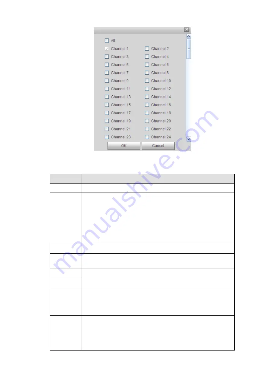
Figure 4-117
Please refer to the following sheet for detailed information.
Parameter
Function
Channel
Please select a channel from the dropdown list.
ANR
Check the box here, you can enable ANR function. When the NVR and
IPC connection is abnormal, the recorded file can be saved on the IPC
(Please make sure your IPC has storage media and support this
function). The NVR can download record from the IPC once the
network connection is OK.
You can set the max download record file length. Once the
disconnection is more than the threshold you set here, NVR only
downloads the specified record period.
Pre-record
Please input pre-record time here. The value ranges from 0 to 30.
Redundancy Check the box here to enable redundancy function.
Please note this
function is null if there is only one HDD.
Snapshot
Check the box here to enable snapshot function.
Holiday
Check the box here to enable holiday function.
Setup
Click the Setup button, you can set record period. See Figure 4-116.
There are six periods in one day. If you do not check the date at the
bottom of the interface, current setup is for today only.
Please click Save button and then exit.
Copy
Copy function allows you to copy one channel setup to another. After
setting in channel, click Copy button, you can go to interface Figure
4-117. You can see current channel name is grey such as channel 1.
Now you can select the channel you want to paste such as channel
5/6/7. If you want to save current setup of channel 1 to all channels,
you can click the first box “ALL”. Click the OK button to save current
Summary of Contents for ELITE Network IP Series
Page 1: ...64 Channel 4K Hot Swap NVR NVR ELHS 64 4K DH...
Page 108: ...Figure 3 92 Figure 3 93...
Page 131: ...Figure 3 111 Figure 3 112 Figure 3 113...
Page 144: ...Figure 3 126 Figure 3 127...
Page 146: ...Figure 3 129 Click draw button to draw the zone See Figure 3 130 Figure 3 130...
Page 149: ...Figure 3 133 Click Draw button to draw a zone See Figure 3 134 Figure 3 134...
Page 154: ...Figure 3 139 Click draw button to draw the zone See Figure 3 140...
Page 172: ...Figure 3 157 Figure 3 158...
Page 173: ...Figure 3 159 Figure 3 160...
Page 176: ...Figure 3 164 Figure 3 165...
Page 211: ...Figure 3 199...
Page 234: ...Figure 3 227 Step 2 Click Add group Enter add group interface See Figure 3 228 Figure 3 228...
Page 298: ...Figure 4 56 Figure 4 57...
Page 304: ...Figure 4 62 Figure 4 63...
Page 305: ...Figure 4 64 Figure 4 65...
Page 330: ...Figure 4 101 Figure 4 102...
Page 339: ...Figure 4 115 Figure 4 116...
Page 359: ...Figure 4 144 Note For admin you can change the email information See Figure 4 145...


