Parameter
Function
write.
Trap address
The destination address of the Trap information from the proxy
program of the device.
Trap port
The destination port of the Trap information from the proxy
program of the device. It is for the gateway device and the
client-end PC in the LAN to exchange the information. It is a
non-protocol connection port. It has no effect on the network
applications. It is a UDP port not TCP port. The value ranges
from 1 to 165535. The default value is 162.
Read-only user
It only supports reading function when logging in the device
with this user account.
Authentication
mode
Including two modes: MD5 and SHA. The system can
automatically recognize it after enabled.
Read-write user
It supports reading and writing when logging in the device with
this user account.
Password
The password for authentication and encryption. It shall be no
less than 8 characters.
Encryption Type
Select the encryption mode. The default mode is CBC-DES.
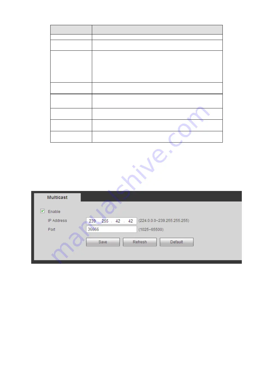
4.6.2.9 Multicast
The multicast interface is shown as in Figure 4-48.
Multicast is a transmission mode of data packet. When there is multiple-host to receive the same data
packet, multiple-cast is the best option to reduce the broad width and the CPU load. The source host
can just send out one data to transit. This function also depends on the relationship of the group member
and group of the outer.
Figure 4-48
4.6.2.10 Auto Register
The auto register interface is shown as below. See Figure 4-49.
This function allows the device to auto register to the proxy you specified. In this way, you can use the
client-end to access the NVR and etc via the proxy. Here the proxy has a switch function. In the network
service, device supports the server address of IPv4 or domain.
Please follow the steps listed below to use this function.
Please set proxy server address, port, and sub-device name at the device-end. Please enable the auto
register function, the device can auto register to the proxy server.
Summary of Contents for ELITE Network IP Series
Page 1: ...64 Channel 4K Hot Swap NVR NVR ELHS 64 4K DH...
Page 108: ...Figure 3 92 Figure 3 93...
Page 131: ...Figure 3 111 Figure 3 112 Figure 3 113...
Page 144: ...Figure 3 126 Figure 3 127...
Page 146: ...Figure 3 129 Click draw button to draw the zone See Figure 3 130 Figure 3 130...
Page 149: ...Figure 3 133 Click Draw button to draw a zone See Figure 3 134 Figure 3 134...
Page 154: ...Figure 3 139 Click draw button to draw the zone See Figure 3 140...
Page 172: ...Figure 3 157 Figure 3 158...
Page 173: ...Figure 3 159 Figure 3 160...
Page 176: ...Figure 3 164 Figure 3 165...
Page 211: ...Figure 3 199...
Page 234: ...Figure 3 227 Step 2 Click Add group Enter add group interface See Figure 3 228 Figure 3 228...
Page 298: ...Figure 4 56 Figure 4 57...
Page 304: ...Figure 4 62 Figure 4 63...
Page 305: ...Figure 4 64 Figure 4 65...
Page 330: ...Figure 4 101 Figure 4 102...
Page 339: ...Figure 4 115 Figure 4 116...
Page 359: ...Figure 4 144 Note For admin you can change the email information See Figure 4 145...


