During the whole process (the master device is working properly>master device is malfunction>master
device becomes work properly again), you can use this virtual IP to access the device all the time.
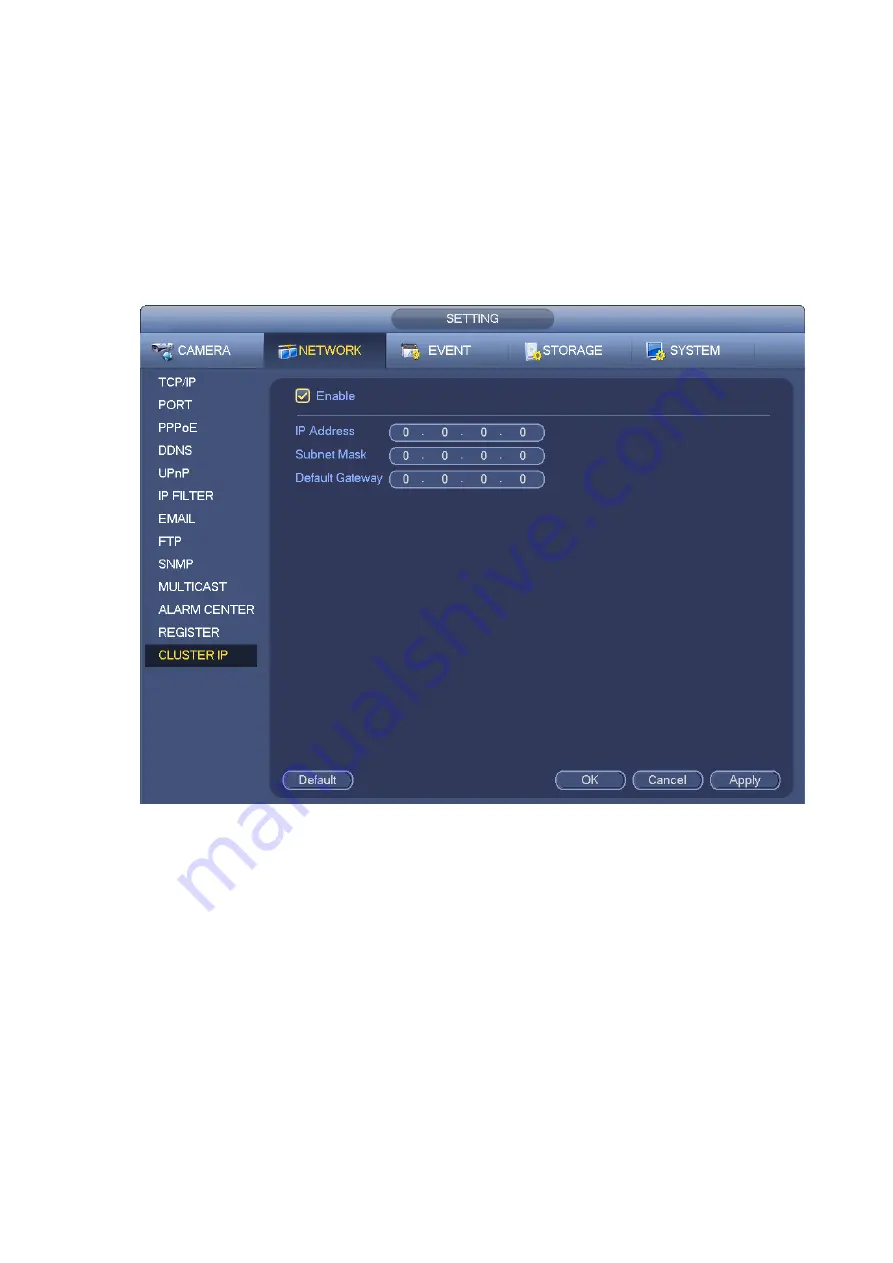
It is for you to set IP address, subnet mask, gateway and etc of the Switch. See Figure 3-188.
Please check the box to enable this function and then input corresponding IP address, subnet mask,
default gateway. Click OK button to complete the setup. The virtual IP here is for the master device.
Note
The IP in the TCP/IP interface is for cluster internal control (It is mainly for the mater device and slave
device internal interactive). The virtual IP you set here is for cluster external control (It is for external
network connection).
Figure 3-188
3.11.1.13 P2P
P2P is a kind of convenient private network penetration technology. You do not need to apply for dynamic
domain name, doing port mapping or deploying transit server. You can add NVR devices through the
below way to achieve the purpose of managing multiple NVR devices at the same time. For detailed
operation to configure P2P, please refer to chapter 3.4.3 P2P.
3.11.2
Network Test
In this interface, you can see network test and network load information.
3.11.2.1 Network Test
From main menu>Info-Network>Test, the network test interface is shown as in Figure 3-189.
Destination IP: Please input valid IPV4 address and domain name.
Test: Click it to test the connection with the destination IP address. The test results can display
Summary of Contents for ELITE Network IP Series
Page 1: ...64 Channel 4K Hot Swap NVR NVR ELHS 64 4K DH...
Page 108: ...Figure 3 92 Figure 3 93...
Page 131: ...Figure 3 111 Figure 3 112 Figure 3 113...
Page 144: ...Figure 3 126 Figure 3 127...
Page 146: ...Figure 3 129 Click draw button to draw the zone See Figure 3 130 Figure 3 130...
Page 149: ...Figure 3 133 Click Draw button to draw a zone See Figure 3 134 Figure 3 134...
Page 154: ...Figure 3 139 Click draw button to draw the zone See Figure 3 140...
Page 172: ...Figure 3 157 Figure 3 158...
Page 173: ...Figure 3 159 Figure 3 160...
Page 176: ...Figure 3 164 Figure 3 165...
Page 211: ...Figure 3 199...
Page 234: ...Figure 3 227 Step 2 Click Add group Enter add group interface See Figure 3 228 Figure 3 228...
Page 298: ...Figure 4 56 Figure 4 57...
Page 304: ...Figure 4 62 Figure 4 63...
Page 305: ...Figure 4 64 Figure 4 65...
Page 330: ...Figure 4 101 Figure 4 102...
Page 339: ...Figure 4 115 Figure 4 116...
Page 359: ...Figure 4 144 Note For admin you can change the email information See Figure 4 145...


