background image

Setting the Gateway Parameters 

5-31 

Setting WAN Call Routing Parameters 

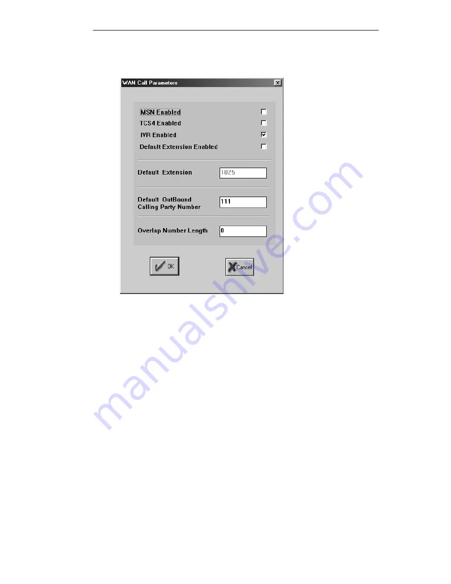
The WAN Call Parameters screen allows you to set the routing methods supported for this 
ISDN BRI WAN port.  


Figure 33 - WAN Call Parameters screen 

The Gateway supports four incoming call routing methods in the following order of priority: 
MSN (Multiple Subscriber Numbering), TCS4, IVR (Interactive Voice Response) and 
Default Extension. For information on call routing methods, see “Incoming Call Routing 
Methods” in Chapter 2, “Overview.” 

The WAN Call Parameters screen allows you to enable or disable these incoming call 
routing methods. When the check box by the routing method is selected, the routing method 
is enabled. 

For information on call routing methods, see (“Incoming Call Routing Methods” in Chapter 
2, “Overview”). 


Summary of Contents for L2W-323

Page 1: ...P N 61285 00001 Rev A L2W 323 GATEWAY User Guide ...

Page 2: ......

Page 3: ... the program s described in this documentation at any time If there is any software on removable media described in this publication it is furnished under a license agreement included with the product as a separate document If you are unable to locate a copy please contact RADVision Ltd and a copy will be provided to you Unless otherwise indicated RADVision registered trademarks are registered in ...

Page 4: ......

Page 5: ...Panel 1 5 Overview The OnLAN 323 Product Series 2 1 OnLAN 323 Product Collaboration 2 2 L2W 323 Gateway and MCU 323 2 2 L2W 323 Gateway and VIU 323 2 3 An Introduction to H 323 2 4 What is the H 323 Standard 2 4 H 323 Network Components 2 4 Integrating the L2W 323 Gateway into Your Network 2 6 Multimedia Conferencing Application 2 6 Voice Over IP VoIP Application 2 7 Types of Connections 2 8 Under...

Page 6: ...ule 3 3 Uploading the BRI Module Driver 3 4 Mounting the Gateway in a 19 inch Rack 3 4 Installing More than One Unit 3 5 Connecting the Cables 3 5 Power Connection 3 5 LAN Connection 3 6 WAN Connection 3 7 Checking for Correct Operation 3 9 Connecting to the Console Port 3 9 Next Step Configuration 3 12 Preparing for Configuration Planning the Configuration 4 1 Prerequisites 4 1 Setting Up the Con...

Page 7: ... 14 Setting Unit Identification Parameters 5 15 Setting Miscellaneous Parameters 5 16 Setting Miscellaneous WAN Parameters 5 20 Setting LAN Port Parameters 5 21 Setting Gateway Services 5 23 Setting WAN Port Parameters 5 26 Saving and Uploading the Gateway Parameters 5 39 Making a Call Through the L2W 323 Gateway 5 41 Advanced Gatekeeper Configuration Overview 6 1 Advanced Services Definition 6 1 ...

Page 8: ...32 Distance Settings 6 32 Disabling the Gatekeeper Function when there are Ongoing Calls 6 34 Using the L2W 323 Gateway Overview 7 1 Internetwork Dialing 7 2 Dialing Out to the WAN through the Gateway 7 2 Dialing In to the LAN through the Gateway 7 5 Intranetwork Dialing 7 9 Dialing from One LAN Endpoint to Another 7 9 Making Voice Calls over the IP Network 7 14 Far End Camera Control 7 16 Servici...

Page 9: ... From the Console Port 9 3 Problems Using the L2W 323 Gateway 9 4 Making Calls 9 4 Receiving Calls 9 7 Changing the Password 9 10 IP Address Problems 9 11 Defining IP Addresses via a Terminal Session 9 11 Cable Connectors and Pin outs RJ 45 LAN Port A 1 LAN 10 100Base T RJ 45 Connector A 1 Straight Through Ethernet Cable A 1 Crossover Ethernet Cable A 2 ISDN S Interface A 2 RJ 45 8 pin Receptacle ...

Page 10: ...D 1 Audio Coding D 1 LEDs D 2 Physical Dimensions D 2 Power Supply D 2 Environmental Requirements D 2 Certifications D 2 FCC Part 68 Customer Instructions FCC and Industry Canada Compliance E 1 FCC Registration and Requirements E 1 Service E 1 FCC Rules Part 15 E 1 FCC Rules Part 68 E 1 Equipment Attachment Limitations E 4 Ringer Equivalence Number REN E 4 Equipment Attachment Limitations E 4 Glos...

Page 11: ... Figure 18 The Application Parameters screen for Gatekeeper configuration 5 8 Figure 19 Gatekeeper Services Definition Table screen with default services 5 11 Figure 20 Network Control screen 5 12 Figure 21 Selecting the source file for the Gateway configuration parameters 5 14 Figure 22 Unit Identification screen 5 15 Figure 23 Miscellaneous Parameters screen 5 16 Figure 24 Presentation Restricte...

Page 12: ... GK Parameters screen 6 23 Figure 49 Network Topology Table screen 6 25 Figure 50 Subnet Parameters screen 6 26 Figure 51 Network Control screen 6 28 Figure 52 Advanced Settings screen 6 31 Figure 53 Making voice calls with ISDN PSTN phones over an IP network 7 14 Figure 54 Software Upload Utility window for OnLAN L2W 323 8 2 Figure 55 Upload Status Window for the OnLAN L2W 323 8 3 Figure 56 The R...

Page 13: ...work components Gateway applications collaboration with other RADVision products and descriptions of how the Gateway and Gatekeeper work Chapter 2 Installation procedures and a description of the power up sequence Chapter 3 Recommendations on how to plan the configuration and information on running Setup and installing and using the Configuration software Chapter 4 Procedures for configuring the G...

Page 14: ...instructions Warning Information that alerts you to potential danger to yourself or the Gateway Menu commands buttons and text boxes Menu commands button names and text boxes appear in bold Glossary terms The first time a Glossary entry appears in the text it is bolded Related Documentation The L2W 323 Gateway documentation set includes a Quick Start Guide providing information for installing and ...

Page 15: ...ducing the L2W 323 Gateway This chapter introduces the L2W 323 Gateway It covers the following topics Introducing the L2W 323 Gateway Gateway Features Internal Gatekeeper Features Gateway Physical Description ...

Page 16: ......

Page 17: ...lates between the H 323 and the H 320 protocols interconnecting via ISDN voice and videoconferencing clients on IP networks to Voice and videoconferencing clients on other IP networks ISDN compliant legacy H 320 videoconferencing Room Systems Telephones on the ISDN or the Public Switched Telephone Network PSTN network The RADVision L2W 323 Gateway has an internal Gatekeeper Together the Gateway an...

Page 18: ...ing H 281 Provides faster T 120 up to 70 4 Kbps Provides four voice transcoders Provides Fast Ethernet support 10 100Base T Provides password protection for FTP and Telnet access remote diagnostics Supports multicast discovery for the gatekeeper Version 1 3 The L2W 323 Gateway has the following features An embedded system One or two of the following WAN modules in any combination ISDN BRI providin...

Page 19: ... optional feature Supports line echo cancellation Front panel LED display Self test during power on No user intervention required for operation Simple configuration and setup via a Windows application Diagnostics feature Replaceable and modifiable IVR messages using the IVR Recording utility Easy software upgrades from a remote site using TFTP into flash memory T 120 support Auto detection of call...

Page 20: ...neous calls Supports the registration of up to 150 endpoints Supports optional zone management through the definition of terminals Supports multiple gatekeeper operation for large networks Supports logical network division for optimal call routing Supports multicast discovery for the gatekeeper Gateway Physical Description This section describes the physical features of the L2W 323 Gateway front a...

Page 21: ...D Indications in Chapter 9 Troubleshooting the L2W 323 Gateway Console Port You can connect the RS 232 console serial port directly to a terminal or to a remote terminal via modem for diagnostics monitoring and configuration The console port has a female DB9 receptacle For information on connecting this port see Connecting to the Console Port in Chapter 3 Installing the L2W 323 Gateway Rear Panel ...

Page 22: ...an install any combination of two of the following modules ISDN BRI dual port module V 35 DTE dual port module V 35 DCE dual port module The following illustrations demonstrate possible WAN module combinations PORT 1 PORT 2 PORT 1 PORT 2 V35 V 25bis 2 port Module V35 V 25bis 2 port Module PORT 1 PORT 2 ISDN 2 BRI Module PORT 1 PORT 2 ISDN 2 BRI Module PORT 2 V35 RS 366 V 25bis 2 port Module ISDN 2...

Page 23: ...ically the L2W 323 Gateway It covers the following topics Overview The OnLAN 323 Product Series OnLAN 323 Product Collaboration An Introduction to H 323 Integrating the L2W 323 Gateway into Your Network Understanding the L2W 323 Gateway Understanding the Internal Gatekeeper ...

Page 24: ......

Page 25: ... MCU 323 Multipoint Conference Unit allows users to spontaneously initiate voice only or full multimedia multipoint conferences at rates ranging from 64 Kbps to 1 5 Mbps The MCU 323 also provides audio mixing G 711 A µ Law video switching H 261 CIF QCIF voice activated and simple monitoring of conferences using a Web browser The VIU 323 Video Interface Unit is a self contained terminal adapter tha...

Page 26: ... the WAN to participate in a mixed WAN LAN multipoint multimedia conference with endpoints on the IP based LAN For example an H 320 terminal on the WAN wants to participate in a multipoint conference with H 323 endpoints on the LAN The H 320 WAN terminal can either join the multipoint conference by dialing to the Gateway or be invited into the conference by one of the participating endpoints on th...

Page 27: ...ublic network The VIU 323 acts as a terminal adapter for the H 320 room system connecting it to the LAN and the L2W 323 Gateway treats the VIU 323 as any H 323 endpoint making it possible for the H 320 room system to communicate with terminals on the ISDN network LAN IP phone L2W 323 Gateway H 323 Terminal ISDN H 320 Terminal VIU 323 H 320 Room System V 35 Figure 5 H 320 room system communicating ...

Page 28: ...on the LAN that provide for real time two way communications Most H 323 terminals are desktop computers running H 323 compliant software All terminals must support voice communications while video and data are optional However if these other media are supported H 323 specifies what modes of operation are required so that all terminals supporting video and or data can work seamlessly together Gatew...

Page 29: ...processing of audio video and or data bits Terminals gateways and MCUs are also known as H 323 endpoints The collection of all terminals gateways and MCUs managed by a single gatekeeper comprise an H 323 Zone Between H 323 and H 320 H 320 is the ITU standard for video conferencing over digital lines like ISDN The standard describes recommendations for both multipoint and point to point video confe...

Page 30: ...based LAN to communicate with an H 320 terminal an ISDN or a regular phone on a circuit switched public network without having to connect directly to these networks as illustrated by the following figure LAN IP phone L2W 323 Gateway H 323 Terminal H 323 Terminal ISDN H 320 Terminal Phone Phone PSTN Figure 6 Multimedia conferencing via the Gateway The L2W 323 Gateway allows all your company s LAN t...

Page 31: ...eway Phone Phone Phone Phone H 320 Terminal PBX PBX ISDN H 320 Terminal Figure 7 Voice over IP communication via Gateways It is not unusual for companies and corporations today to be dispersed over several continents This drastically increases long distance phone expenses and one of the ways companies are dealing with this growing expense is through Voice over IP technologies Using your IP data ne...

Page 32: ... increase the number of WAN connections and available channels LAN Connections The L2W 323 Gateway has one 10 100Base T auto sensing RJ 45 LAN connection The L2W 323 Gateway connects to a LAN segment via a direct connection to a 10 100Base T hub or switch LAN IP phone L2W 323 Gateway H 323 Terminal ISDN H 323 Terminal Router Router H 323 Terminal H 323 Terminal IP phone Figure 8 Connecting more th...

Page 33: ... If the ISDN line supplied by your Central Office has a U interface in the United States an NT1 is required to terminate the ISDN line and convert it to an S T interface for the L2W 323 Gateway The ISDN BRI module connects directly to a wall socket PBX or NT1 if required WAN V 35 DTE DCE Connections The V 35 DTE and V 35 DCE dual port modules provide two V 35 DTE connections or two V 35 DCE connec...

Page 34: ...d V 25bis V 25bis inband dialing allows the sending of control signals during a call over the same frequency as the data This is an advantage over RS 366 outband dialing where the control signals are transmitted outside of the data signal and once the call is connected control signals can no longer be transmitted When connected to a modem the dialing protocol is a dedicated one The L2W 323 Gateway...

Page 35: ...e ISDN the Gateway provides other functions to LAN endpoints dialing out through ISDN and circuit switched WAN terminals dialing into the LAN These functions include DTMF Dual Tone Multi Frequency detection and generation Call transfer for LAN endpoints Audio transcoding Echo cancellation Gateway Services The Gateway WAN interfaces provide several types of connections including voice calls 1B or 2...

Page 36: ...ndpoint on the LAN it identifies the service prefix at the beginning of the dialed string and routes the call through the appropriate WAN port The L2W 323 Gateway tries to connect the call to the destination terminal or phone Incoming Call Routing Methods WAN terminals or phones access the Gateway via phone numbers The Gateway WAN port is directly or indirectly connected to an ISDN line that is as...

Page 37: ...corresponding LAN endpoint The Gateway can also route an incoming video call originating at an H 323 endpoint on a LAN via TCS4 when this endpoint is connected to a gateway The Gateways can be either on the same LAN different LAN segments or on different LANs connected via modems For more information see Dialing In to the LAN through the Gateway in Chapter 7 Using the L2W 323 Gateway IVR Interacti...

Page 38: ...he quality and bit rate of the audio they provide G 711 provides toll quality audio at 64 Kbps G 728 provides near toll quality audio at 16 Kbps and G 723 1 provides voice quality audio at 5 3 or 6 3 Kbps Usually WAN endpoints have G 711 and G 728 codecs while LAN endpoints have G 711 and G 723 1 codecs By performing transcoding between these audio protocols the Gateway can optimize the audio band...

Page 39: ...on 2 defines a specific information field for passing on DTMF tones The L2W 323 Gateway uses the specified field to pass on DTMF tones to and from the WAN Call Setup Supported Features The L2W 323 Gateway also supports the following call setup information Presentation Restricted for WAN to LAN calls The Presentation Restricted field is a RADVision call setup feature that when enabled instructs the...

Page 40: ...tekeeper functions as an overall network administrator and provides the necessary address translation enabling LAN endpoints to communicate with each other and with the other H 323 components on the network The Gatekeeper also enables outbound communication with terminals and phones on the ISDN public network Note All references made to the RADVision Gatekeeper relate to the internal gatekeeper If...

Page 41: ... can dynamically register with the Gatekeeper By predefining endpoints you can distinguish between endpoints for example allowing predefined endpoints to use certain services while other endpoints would not be able to use them RAS Supporting Endpoint Registration When you activate an H 323 endpoint that supports the RAS protocol it registers with the Gatekeeper and goes online The Gatekeeper now k...

Page 42: ...ne numbers and or terminal IDs names The Gatekeeper can translate between the IP address and the corresponding aliases This enables users to dial a number or character string when dialing to other endpoints instead of the IP address When you want to reach another endpoint in the Gatekeeper zone simply dial that endpoint phone number or ID The Gatekeeper matches the alias with a corresponding IP ad...

Page 43: ...ix 1 and 2 Acts like an area code to allow users from other zones to reach this Gatekeeper zone You can define two different zone prefixes for each Gatekeeper When no zone prefixes are defined for the network Gatekeepers all prefixes endpoint numbers and aliases must be unique across all zones When one of the zone prefixes is defined calls from other zones cannot reach this zone unless they dial t...

Page 44: ...defined with this service disabled Working with Several Gatekeepers The internal Gatekeeper can operate with other Gatekeepers in the H 323 network if you configure it to recognize the Gatekeepers of other zones This is achieved by creating a table listing all other Gatekeepers in the network that the current Gatekeeper can access through IP unicast These Gatekeepers are Neighbor Gatekeepers of th...

Page 45: ... the Max Distance or Default Distance of the endpoint is equal to or larger than the Neighbor Distance parameter Note To avoid distance limitations across the network you can set all distance parameters to 0 Optimizing Call Routing on the H 323 Network You can divide the network into islands allowing the Gatekeeper to direct calls through optimal routes and to avoid slow network connections or bot...

Page 46: ... provided by both of the Gateways in the zone the Gatekeeper first routes the call to the Gateway in Island A This connection is fast as it does not pass through the slow network router path If the WAN port of the Gateway in Island A is not available the Gatekeeper routes the call via the router to the Gateway in Island B When you do not define islands the Gatekeeper routes the call to the first a...

Page 47: ...L2W 323 Gateway supports Call Transfer when operating with a RADVision or third party gatekeeper for incoming calls from a phone on the WAN to a LAN endpoint The LAN endpoint can choose to transfer the call to another LAN endpoint or back to a WAN phone in the latter case the Gateway continues to be part of the call and at least two of the Gateway bearer channels are used for the transferred call ...

Page 48: ......

Page 49: ...on a 19 inch rack connect all the cables and check for correct operation It covers the following topics Package Contents Site Considerations Installing the WAN Modules Mounting the Gateway in a 19 inch Rack Installing More than One Unit Connecting the Cables Next Step Configuration ...

Page 50: ......

Page 51: ...your local distributor Site Considerations The Gateway is suited for an office environment where it can be rack mounted with your other network equipment or free standing Before deciding where to mount the L2W 323 Gateway ensure that The Gateway is close to An available WAN connection to ISDN lines an IMUX a modem or a terminal adapter depending on the WAN modules you ordered with the Gateway Avai...

Page 52: ...N Module Description MW BRI 2 EC Enables you to make videoconference and voice calls via the Gateway over the WAN using BRI ISDN services and supports Line Echo Cancellation for Voice Calls V 35 DTE Enables you to videoconference via the Gateway over the WAN at high bandwidths 64 Kbps and above and to connect to ISDN or non ISDN networks through access equipment V 35 DCE Enables you to videoconfer...

Page 53: ...serting the Module The WAN module is installed in the rear panel of the Gateway using one of the available slots Currently only MW1 and MW2 are available MW3 and MW4 are for future versions MW 3 MW 1 MW 4 MW 2 LAN 1 LAN 2 LAN 3 LAN 4 POWER 100 240 VAC PORT 1 MW V 35 2T PORT 2 MW BRI 2 PORT 1 PORT 2 l 0 10 100 M LAN Figure 10 Rear Panel with a BRI and a V 35 module To insert the module into the Gat...

Page 54: ... in Chapter 8 Servicing the Gateway Note The V 35 modules have built in drivers Mounting the Gateway in a 19 inch Rack You can install the Gateway in most 19 inch racks The rack mounting kit supplied with the Gateway includes two 19 inch brackets Two screws and two flat washers are supplied with each bracket To mount the L2W 323 Gateway in a rack 1 Place the Gateway right way up on a hard flat sur...

Page 55: ...e sure these protective pads are in place when placing units one on top of another Connecting the Cables You must connect the Gateway to a power outlet a 10 100Base T LAN hub or switch and a WAN connection BRI ISDN or V 35 connection unit Power Connection The L2W 323 Gateway receives AC power through a standard power cable with a grounded three prong plug Before you connect the L2W 323 to the powe...

Page 56: ...plex 10 Mbps Ethernet connections You connect the Gateway to the LAN via a 10 100Base T hub Before you connect a new Gateway to the LAN it is recommended to connect the Gateway to a PC with a 10 100Base T LAN interface to assign the Gateway its new IP address For this connection a crossover Ethernet cable is required LAN cables are not provided with the L2W 323 Gateway The LAN cable you use depend...

Page 57: ...s on the modules you ordered Module Connectors ISDN BRI S T MOBI S TE Two RJ 45 connectors V 35 DTE Two 26 pin D type connectors V 35 DCE Two 26 pin D type connectors ISDN BRI WAN Connection You can connect the ISDN interface directly to a BRI ISDN socket or indirectly via a PBX The BRI modules MW BRI 2 MW BRI EC ships with the appropriate ISDN cables The BRI module has an S T interface If the ISD...

Page 58: ...ector of the V 35 RS 366 cable to one of the V 35 DTE ports 2 Connect the V 35 male connector and the RS 366 male connector on the other end of the cable to the connecting device To connect the Gateway V 35 DTE ports to a modem in a dedicated connection 1 Connect the D type 26 pin male connector of the V 35 cable to one of the V 35 DTE ports 2 Connect the V 35 male connector on the other end of th...

Page 59: ...rmal indications see LED Indications in Chapter 9 Troubleshooting the L2W 323 Gateway Connecting to the Console Port The console serial port on the front panel of the Gateway allows you to connect the L2W 323 Gateway to a PC or a modem for Local or remote diagnostics see Monitoring the Gateway in Chapter 8 Servicing the Gateway Special configuration of IP addresses and subnet masks see IP Address ...

Page 60: ... terminal software used on the PC has the following communications parameters Baud rate 9600 Data bits 8 Stop bits 1 Parity none Flow control none 2 Connect the 9 pin male connector of the cable to the Gateway console port 3 Connect the 9 pin female connector to the PC serial port 4 Run the Hyper Terminal or other terminal emulator and press Ctrl X to restart the Gateway Note When the Gateway is c...

Page 61: ...er on Carrier Detect CD on Data Terminal Ready DTR on Echo enabled on To connect the Gateway console port to a modem 1 Verify the modem configuration parameters are as specified in Connecting through a Modem 2 Connect the 9 pin male connector of the cable to the Gateway console port 3 Connect the 25 pin female connector on the other end of the cable to the modem 4 For remote diagnostics create a n...

Page 62: ...nal with the OnLAN Configure 323 configuration software Basic Configuration Guides you through the essential configuration procedures for the Gateway and the Gatekeeper Once these are complete your Gateway is ready for operation and you can make LAN to WAN and WAN to LAN calls Advanced Gatekeeper Configuration Guides you through the configuration options for the Gatekeeper not covered in the Basic...

Page 63: ...n This chapter describes several pre configuration considerations and procedures It covers the following topics Planning the Configuration Setting Up the Configuration Station Running Setup Assigning an IP Address to a New Gateway ...

Page 64: ......

Page 65: ... address of one new unit at a time We recommend you assign an IP address to a new Gateway before you connect it to the network This is achieved by connecting the Gateway to a PC with a crossover Ethernet cable After you assign an IP address to the new Gateway you can connect it to the network This is a cautionary measure that prevents accidentally changing the IP addresses of other RADVision units...

Page 66: ... one B channel Video 1 or 2 x 64 Kbps calls 82 For videoconferencing calls using 1B channel or 2B channels Video 1 or 2 x 56 Kbps calls 83 For videoconferencing calls using 1B channel or 2B channels on restricted ISDN V 35 256 Kbps calls 84 For high bandwidth videoconferencing calls over V 35 or BRI ports V 35 224 Kbps calls 85 For high bandwidth videoconferencing calls over V 35 or BRI ports for ...

Page 67: ...Gatekeeper or the NT based NGK 100 you will benefit from value added functions as well as seamless operation with the Gateway For more information on the RADVision NGK 100 Gatekeeper please contact your distributor Prerequisites Check list Make sure you have considered the following items before you begin the configuration Prepare a designated IP address to assign to the Gateway Make sure you know...

Page 68: ...ing products L2W 323 Gateway BRI L2W 323P Gateway PRI MCU 323 Multipoint Conferencing Unit VIU 323 Terminal Adapter Note For instructions on running Setup see page 4 6 Upgrading If you have a previous version of the L2W 323 Gateway copy all ini files in the OnLAN Configure 323 configuration directory to a temporary folder before performing the upgrade For Gateway versions 1 6 and higher the defaul...

Page 69: ...iguration software backward compatible for all previously released Gateway versions The IVR Recording Utility to change IVR Interactive Voice Response messages The Software Upload Utility to upload flash files which contain the Gateway software upgrade Note You do not have to select a product if you don t Setup only installs utilities Setup Type Setup offers three options for copying RADVision OnL...

Page 70: ...layed 3 Follow the Setup prompts click Next to continue to the following prompt 4 We recommend you click Yes to read the Readme file when finished close the file 5 To copy the product user guide and utilities select L2W 323 Gateway and any other product you want to install and click Next alternatively to copy utilities only leave all check boxes blank and click Next 6 Select the destination folder...

Page 71: ...its the Configuration program without saving your changes Next Alt N Moves to a subsequent screen saving any changes you made Prev Alt P Moves to a previous screen If you exit a dialog box using Prev changes you make to the information in the dialog box are saved Finish Alt F Allows you to save the configuration settings in a file and upload these settings to the Gateway Detect Alt D Sends a broad...

Page 72: ...ts the dialog box The saved tables contain only static data that is both readable and writeable For the Gatekeeper dynamic only registration information is not saved Cancel Returns to the previous dialog box without saving any changes you made to the current dialog box In a Confirmation box Yes Alt Y Saves the parameters and proceeds to the next screen No Alt N Returns to the previous screen The c...

Page 73: ...23 Gateway To assign an IP address to the Gateway 1 With the Gateway is turned off connect the Gateway LAN port to the configuration PC with a crossover Ethernet cable then turn the Gateway power switch on 2 On the PC run the OnLAN Configure 323 configuration software The Select Unit screen appears and the Unit IP list box is empty 3 In the Unit IP text box type the IP address you want to assign t...

Page 74: ... to the LAN via a 10 100Base T hub or switch 6 Connect the PC to the LAN Note If you experience problems configuring the IP address see IP Address Problems in Chapter 9 Troubleshooting the L2W 323 Gateway Now the Gateway is ready to be configured To begin configuration go to Chapter 5 Basic Configuration ...

Page 75: ...This chapter describes the basic configuration options of the L2W 323 Gateway It covers the following topics Basic Configuration Options Selecting the Gateway Unit Setting the Gatekeeper Mandatory Parameters Setting the Gateway Parameters Saving and Uploading the Gateway Parameters Making a Call Through the L2W 323 Gateway ...

Page 76: ......

Page 77: ...ces Select the Unit to Configure No Disable Gatekeeper Set Gateway Parameters Verify LAN Port Parameters Define Gateway Services Yes Set Miscellaneous Parameters Select Configuration Source Save Configuration Upload Parameters to Unit Yes No The configuration is saved to the specified file Yes The Gateway restarts with new parameters No Configure another unit Yes The Select Unit screen displays No...

Page 78: ...tion 1 From the configuration PC run the OnLAN Configure 323 configuration software 2 The Select Unit screen appears with a list of all the RADVision units on the network segment Figure 13 Select Unit screen 3 If the IP you assigned to the Gateway in Assigning an IP Address to a New Gateway Chapter 4 Preparing for Configuration does not appear in the Select Unit screen check that There is no route...

Page 79: ...he PC is connected The new L2W 323 Gateway is the only new RADVision unit on the network Turn off all other new RADVision units that do not appear in the Select Unit screen before you proceed 2 Follow steps 1 3 in Assigning an IP Address to a New Gateway Chapter 4 Preparing for Configuration Note If you have other RADVision units on the network and the Unit IP list box is empty check that the IP a...

Page 80: ...pe GWrv in the Password text box the password is case sensitive If this is not a first time configuration and you changed the default password type your new password Figure 14 Enter Password Screen 2 Click Next The Configuration Source screen is displayed Figure 15 Configuration Source screen ...

Page 81: ...two digits of the unit software version The ellipsis button displays the full software version and other software related information For more information see Viewing Software Version Details page 5 5 The middle and lower area of the Configuration Source screen contain parameters that allow you to Modify the unit configuration password See Modifying the Password page 5 6 Access the internal Gateke...

Page 82: ...n displays the version number of the internal Gatekeeper Stack Version displays the full version number of the H 323 protocol stack used by the unit MIB Version displays the SNMP proprietary RADVision MIB version used by the unit Modifying the Password You should change the default L2W 323 Gateway configuration access password The password can have a maximum of 16 characters and is case sensitive ...

Page 83: ... GWrv The password is case sensitive 3 In the New Password text box type the new password 4 In the Confirm New Password text box type the new password again for verification 5 Click OK to confirm You return to the Configuration Source screen The next time you access the configuration of this Gateway type your new password at the Enter Password screen If you do not know the old password contact you...

Page 84: ...2 2 Proceed to Setting Parameters for an External Gatekeeper page 5 13 Note Configure mandatory Gatekeeper parameters before you configure the Gateway otherwise you will have to restart the Gateway after configuring the Gatekeeper Accessing the Internal Gatekeeper Parameters To access the Gatekeeper parameters From the Configuration Source screen click Gatekeeper Setup The Gatekeeper Application P...

Page 85: ...or Gatekeepers in a multi zone environment For more information see Multiple Zones in Chapter 6 Advanced Gatekeeper Configuration Network Topology allows you to define the topology of the network to optimize call routing and network usage For more information see Network Topology in Chapter 6 Advanced Gatekeeper Configuration Network Control allows you to set additional parameters that control the...

Page 86: ...oice call 9 For voice only calls over one B channel Video 1 or 2 x 64 Kbps calls 82 For video calls using 1B channel or 2B channels Video 1 or 2 x 56 Kbps calls 83 For video calls using 1B channel or 2B channels on restricted ISDN V 35 256 Kbps calls 84 For high bandwidth video calls over V 35 or BRI ports V 35 224 Kbps calls 85 For high bandwidth video calls over V 35 or BRI ports for restricted ...

Page 87: ...le screen is displayed 3 Select the gkgwbsrv srv file and click OK The Gatekeeper default services corresponding to the Gateway default services appear in the Gatekeeper Services Definition Table 4 From the Services Definition Table screen click OK From the Application Parameters screen click Exit The Configuration Source screen is displayed To edit the default services see Editing the Gatekeeper ...

Page 88: ...etails on disabling the Gatekeeper when it is in use see Disabling the Gatekeeper Function when there are Ongoing Calls in Chapter 6 Advanced Gatekeeper Configuration To disable the Gatekeeper function before you configure the Gateway 1 From the Application Parameters screen click Network Control The Network Control screen is displayed Figure 20 Network Control screen ...

Page 89: ...e the RADVision Gatekeeper that is internal to the L2W 323 Gateway you can use the following gatekeepers A RADVision Gatekeeper that is internal to another RADVision Gateway or MCU 323 A RADVision external Gateway NGK 100 Another H 323 gatekeeper Any gatekeeper that is used must be informed of the services supported by network Gateways in order to forward call requests to these Gateways This is ac...

Page 90: ...nfiguration file with set parameters This is the configuration source file Loading a configuration file simplifies the configuration procedure as you do not have to set so many parameters Selecting the Configuration Source File The configuration software has two default configuration source files for the L2W 323 Gateway Current retrieves the current parameter settings from the Gateway and allows y...

Page 91: ...ings 2 Click Unit Setup to access the Gateway configuration parameters The Unit Identification screen is displayed Setting Unit Identification Parameters The Unit Identification screen displays identification information for the L2W 323 Gateway Figure 22 Unit Identification screen The Unit Identification screen displays the following read only parameters Unit s Name displays the unit s logical nam...

Page 92: ...ou are configuring a Gateway from a remote site not supported in this version To set the Location parameter Type a description of the physical location of the L2W 323 Gateway in the Location field and click Next to continue configuring the Gateway parameters The Miscellaneous Parameters screen is displayed Setting Miscellaneous Parameters In the Miscellaneous Parameters screen you can define sever...

Page 93: ...Voice Response in Chapter 2 Overview The default is 1111 External IVR IP and Port allows you to set the IP address and port number of an external IVR When not using the internal IVR you can define an external IVR for the Gateway For RADVision IVR systems the default port is 1620 Second Number Delimiter allows you to define a delimiter between two numbers for instances when you make an outgoing 2B ...

Page 94: ...IVR operator with the default phone number 1111 For information on registering endpoints see H 323 Endpoint Registration in Chapter 2 Overview 5 If the Gateway has a transcoding card select a priority transcoding method 6 Click Next The LAN Port Settings screen is displayed When using the Gateway internal IVR service proceed to Setting LAN Port Parameters page 5 21 Otherwise follow the steps below...

Page 95: ...stricted Support parameter Presentation Restricted is a RADVision call setup feature When enabled it tells the L2W 323 Gateway to pass the Presentation Restricted field to the RADVision Gatekeeper this conceals the caller s identity from the H 323 endpoint Presentation Restricted Support is enabled by default For more information see Call Setup Supported Features in Chapter 2 Overview ...

Page 96: ...t If you disable this parameter you disable the Gateway s internal inverse multiplexor IMUX functionality and no bonded high bandwidth calls are accepted This means the Gateway can handle more calls of a lower quality Max Call Bandwidth allows you to set the maximum bandwidth allowed for bonded call The following bandwidths are available 128 Kbps 2 x 64 Kbps channels 256 Kbps 4 x 64 Kbps channels ...

Page 97: ...25 LAN Port Settings screen The LAN Port Settings screens display the following parameters Port Number displays the port number you are configuring This is a read only parameter Enabled allows you to enable or disable this port The default for LAN Port 1 is Enabled Port Type displays the type of LAN access method This is a read only parameter MAC Addr displays the hardware Media Access Control add...

Page 98: ...nabled check box 2 In the IP Address text box type the IP address attributed to this port For LAN port 1 this IP is identical to the Gateway IP address and is displayed automatically 3 In the IP Mask field type the relevant network IP Mask 4 In the Description field type a description for the LAN port 5 Click Next until you reach the LAN Parameters screen Note If you change the IP address of LAN p...

Page 99: ...yed Setting Gateway Services From the Services Definition Table screen you can define services for the Gateway Make sure the services you define are also defined for the Gatekeeper For more information see Defining Gatekeeper Services page 5 10 Figure 27 Gateway Services Definition Table screen Figure 27 displays the service settings for the Plug Play source file When you configure the Gateway for...

Page 100: ...eway When you add or delete a service this counter updates automatically Max Entries displays the maximum number of services that can be defined The maximum number is 50 The main area of the Services Definition Table displays the following information about each service Entry displays the number of the service in the table Description this is the description of the service Prefix this is the ident...

Page 101: ...ox type a description for this service 3 In the Call Type list box select the appropriate type of call 4 In the Prefix text box type the prefix for this service 5 From the Max Bit Rate per channel list box select the appropriate value for this service If you are defining a voice only service this parameter is disabled 6 If your lines or the destination lines are restricted n x 56 select the Restri...

Page 102: ...nition Table screen and the Gateway no longer supports this service 2 Click Next The WAN Port Settings screen is displayed Modified or new services are available to LAN endpoints only after you do the following Upload the configuration settings to the Gateway Define the same services for the Gatekeeper Re register the Gateway with the Gatekeeper Setting WAN Port Parameters The WAN Port Settings sc...

Page 103: ... enable this port If you disable this port you will not be able to make or receive calls through the Gateway This port is enabled by default DCE DTE displays whether the WAN module is a DCE or a DTE module This is a read only field Phys STD displays the type of line connected to this WAN port This is a read only field Country allows you to select the country where the ISDN service is installed Cur...

Page 104: ... allows you to set incoming call routing methods for this port For information see Setting WAN Call Routing Parameters page 5 31 Supported Services displays the Supported Services screen allowing you to set the services supported by this port For information see Viewing and Setting Supported Services page 5 32 Advanced displays the Advanced Settings screen See Advanced Settings for the ISDN BRI Po...

Page 105: ...S100 from the Signaling Protocol list SPIDs are not defined if the country selected is Europe Japan or Taiwan You can type one or two SPIDs for the ISDN connection Note When using the 5ESS_PTP protocol SPIDs should be left blank To assign an SPID to an ISDN Connection 1 From the WAN Port Settings ISDN screen click SPID The SPID screen is displayed 2 Type one or two Service Provider Identifications...

Page 106: ...he BRI connection To assign Directory Numbers to an ISDN Connection 1 From the WAN Port Settings ISDN screen click Directory Num The Directory Number screen is displayed 2 Define between one to eight directory numbers DNs per signaling protocol or per SPID and click OK to return to the WAN Port Settings ISDN screen Note Use only the local seven digit number for the DN and do not include the area c...

Page 107: ...ng order of priority MSN Multiple Subscriber Numbering TCS4 IVR Interactive Voice Response and Default Extension For information on call routing methods see Incoming Call Routing Methods in Chapter 2 Overview The WAN Call Parameters screen allows you to enable or disable these incoming call routing methods When the check box by the routing method is selected the routing method is enabled For infor...

Page 108: ...ield it then forwards the whole number to call setup signaling Check with RADVision Technical Support to see if your Gateway version supports this feature Note If the in block dialing method is being used set the overlap number length to zero When you finish click OK to confirm any changes At the WAN Port Settings ISDN screen click Supported Services The Supported Services screen is displayed To e...

Page 109: ...re 64 Kbps 128 Kbps 256 Kbps 384 Kbps and 768 Kbps Restr Mode displays whether the call defined by this service is restricted n x 56 Kbps instead of n 64 Kbps The Support field indicates whether the service is enabled or disabled for the Gateway BRI port A red check mark indicates that the service is enabled Enable Disable allows you to enable or disable a selected service To enable or disable a s...

Page 110: ...WAN terminal if the call is not connected within a few seconds This informs the WAN terminal that the call is not yet connected to the LAN endpoint As a result the WAN terminal continues to hear a ringing sound until the Gateway connects the call Enable Alerting is applicable for voice calls only When Enable Alerting is not selected the Gateway connects a call that is not rejected instead of sendi...

Page 111: ... To change the default Advanced screen settings 1 In the WAN Port Settings ISDN screen click Advanced The Advanced Settings screen displays 2 Clear the Enable Alerting check box if you want to prevent the Gateway from sending Alert messages 3 Select the Enable Layer 1 Line Hunting check box if you wish to use this feature in a non European system 4 Select the Static TEI check box if you want to co...

Page 112: ... of the device connected to this port This parameter is only relevant when you select V 25bis from the Dialing STD list or when you want to define a Dedicated connection The Terminal Adapter Type list includes a number of terminal adapter brands an sw_other and a Dedicated option If the connection device you have connected to this V 35 port does not appear in the list or for some reason the port i...

Page 113: ...this dialing mode the V 35 port does not accept incoming calls GW H320EP DCD CTRL used for Gateway to H 320 terminal dialing where the terminal only asserts DCD when it initiates or receives a call Note If the H 320 terminal connected to the Gateway always asserts DCD and the port is configured to GW H320EP there will be a continuous ongoing call between the Gateway and the H 320 terminal on this ...

Page 114: ...isplay the WAN Parameters screen The WAN Parameters screen summarizes the WAN port parameter settings and is a read only screen Figure 37 WAN Parameters screen If you want to edit settings for the WAN port click No to return to the WAN Port Settings screen Otherwise click Yes to confirm The Save Setup screen is displayed ...

Page 115: ... of the file to which you want to save the configuration parameters 2 Click Yes to confirm The parameters are saved as an ini file to the directory in which the OnLAN Configure 323 configuration software is installed The next time you access this Gateway configuration this file appears in the Source drop down list box of the Configuration Source screen see page 5 14 The Confirm screen is displayed...

Page 116: ...ers a warning is displayed If you choose to upload the parameters anyway the Gateway disconnects all active calls gracefully i e from each endpoint the call appears to have been disconnected at the other endpoint and restarts The Gateway restarts automatically upon uploading the new configuration Wait for the Gateway to complete the restart process before you operate it The unit may take longer to...

Page 117: ...point to the Gatekeeper For information on endpoint registration see H 323 Endpoint Registration in Chapter 2 Overview 2 From this endpoint dial the Gateway service for a video call followed by the phone number of a terminal on the WAN for example dial 82 6457332 where 82 is the Gateway service for a basic rate data call 6457332 is the ISDN phone number of the destination WAN terminal and is the s...

Page 118: ......

Page 119: ...iguration This chapter describes the advanced configuration options of the internal Gatekeeper It covers the following topics Overview Advanced Services Definition Zone Definition Multiple Zones Network Topology Network Control ...

Page 120: ......

Page 121: ... to these terminals Determining which endpoints can register with the Gatekeeper Configure the Gatekeeper to work with other Gatekeepers on the network Dividing the Gatekeeper zone for optimal call routing Setting network administration parameters Note All references to a gatekeeper in this chapter are particular to the internal Gatekeeper Advanced Services Definition You can define advanced servi...

Page 122: ...tup button The Gatekeeper Application Parameters screen is displayed 2 In the Application Parameters screen click the Services Definition button The Gatekeeper Services Definition Table is displayed Figure 39 Gatekeeper Services Definition Table screen 3 Select the built in service you want to define Forward Zone Prefix 1 Zone prefix 2 or Exit Zone and click Edit The Services Definition screen is ...

Page 123: ... that this service has been defined and is available Service Access Control In the basic configuration we made all services available to all endpoints by defining them as both Public and Default This allows all endpoints to access the network services You can narrow this accessibility and distinguish between services by changing the service status to either Public or Default Review your service ac...

Page 124: ...refix Remember that prefixes can be can be up to 31 characters long and valid characters are 0 through 9 and pound asterisk and comma 4 Select the Public and Default check boxes 5 Click OK This service is added to the Services Definition Table To define the service prefix for the terminals in the group as an additional phone number This procedure depends on the registration policy of the terminal ...

Page 125: ...eway service file If this internal Gatekeeper serves several RADVision units you can use the global service file as it is or modify it according to your network needs To load a Gatekeeper default service file 1 From the Services Definition Table screen click Load 2 Select the service file you want to load and click OK 3 If necessary edit these services Click Save to save these settings to a servic...

Page 126: ...n type a description and a prefix and set the access control Default and Public flags Click OK Saving the Service Definitions to a File You can save the services you define in the Services Definition Table to a file To save the Gatekeeper services to a file 1 From the Services Definition Table screen click Save The Save As dialog box is displayed 2 From the Folders list box select the folder in wh...

Page 127: ...sion Gatekeeper can operate in one of two modes open zone and strict zone giving you the choice to control endpoint access to the zone In an open zone mode the Gatekeeper accepts registration from all endpoints for which this Gatekeeper is defined as the default Gatekeeper This mode allows plug and play endpoint additions to the network but does not give you full access control over the zone To co...

Page 128: ...firm In a strict zone mode the Gatekeeper only accepts registration from predefined endpoints This mode does not allow plug and play endpoint additions to the network as you have to predefine any endpoints you want to add Operating in a strict zone mode gives you full access control over the zone Note For information on network control parameters see Network Control on page 6 28 ...

Page 129: ...soft NetMeeting versions 2 x do not support the RAS protocol and have to be predefined with the Gatekeeper For more information see H 323 Endpoint Registration in Chapter 2 Overview In both the strict zone and open zone modes endpoint registration can be either static or dynamic Although the strict zone mode of operation only accepts registration from predefined endpoints this does not mean these ...

Page 130: ...nter updates automatically Max Entries displays the maximum number of endpoints that can be registered with the current Gatekeeper Currently the maximum number is 100 The main area of the Zone Definition Table screen displays the following information about predefined and online endpoints Unit Type the type of unit that is registered with the Gatekeeper Terminal ID the endpoint identities on the I...

Page 131: ...t support the RAS protocol also have to be defined as Online Always and predefined endpoints that support the RAS protocol have to be online online the endpoint is currently dynamically registered with the Gatekeeper When a predefined endpoint is online dynamic registration its status is online predef Always the predefined endpoint is defined as Online Always Predefined endpoints that do not suppo...

Page 132: ...ies screen The Predefined Properties screen allows you to define the registration properties for an endpoint The Predefined Properties screen is also displayed when you edit a predefined endpoint It contains the following read only parameters Predefined if you are editing a predefined endpoint this box is selected Online if you are editing a predefined endpoint that has dynamically registered with...

Page 133: ...ach port Terminal IDs and Phone Numbers These are the aliases you assign to the endpoint You can enter up to five different IDs and five different Phone Numbers Aliases should be unique for endpoints in a zone unless Zone Prefixes are defined For details on setting Zone Prefixes see Defining Gatekeeper Built in Services page 6 2 Additional phone numbers can be identical Allowed Services Opens the ...

Page 134: ...ent parameter see Registration Policy Parameters page 6 29 You can set the Alias Assignment parameter when you finish predefining all endpoints Specifying the Allowed Services You can define which of the services defined for the Gatekeeper this endpoint can use By default a new endpoint is allowed to use all services defined for the Gatekeeper To specify the allowed services for an endpoint 1 From...

Page 135: ...ns Since the Gatekeeper will identify the endpoint by alias and not IP address users can switch workstations without worrying about not receiving their calls See Registration Policy Parameters page 6 29 for details about working in a dynamic IP environment To predefine an endpoint in a dynamic IP environment 1 In the Configuration Source screen click Gatekeeper Setup The Gatekeeper Application Par...

Page 136: ...he properties of a predefined endpoint 1 From the Zone Definition Table select the predefined endpoint you want to edit and click Edit The Predefined Properties screen is displayed 2 Make the necessary changes additions and click OK Viewing the Properties of an Online Endpoint To view the properties of an online endpoint From the Zone Definition Table select the online endpoint whose properties yo...

Page 137: ...he endpoint registered to the Gatekeeper Together with the Port it forms the socket through which the endpoint receives RAS messages from the Gatekeeper Call Signaling IP and Port These are the sockets through which the endpoint expects to get call signaling messages from the Gatekeeper Usually a terminal only has one address while a Gateway may have a number addresses corresponding to its differe...

Page 138: ...2nd the second destination phone number when forwarding 2B calls through the Gateway to a terminal on the WAN Terminal ID the destination ID For more information see Gatekeeper Services in Chapter 2 Overview Supported Services displays the Supported Services screen This is a read only screen that displays a description and the prefix of the services provided by the endpoint to other endpoints Foll...

Page 139: ... time this endpoint registers dynamically with the Gatekeeper the predefined properties you added will be displayed in the Online Properties screen and you can place calls to these phone numbers and IDs Deleting Endpoints You can delete endpoints from the Zone Definition Table Deleted endpoints are not able to make and receive calls unless they re register with the Gatekeeper You may want to delet...

Page 140: ... same directory in which you installed the configuration software 3 In the File name field enter a file name zon is the default file extension for the Zone Definition Table Click OK to confirm Only the static data of the Zone Definition Table is saved to the file Loading a Data File to the Zone Definition Table You can load data files to the Zone Definition Table These are the files you previously...

Page 141: ...s of Gatekeepers in other zones You need to build a table that defines all neighbor Gatekeepers that the current Gatekeeper can access through IP unicast When a call is directed to another zone the Gatekeeper uses neighbors to resolve the destination IP address Note It is important to define all other known Gatekeepers in the network as neighbors to allow calls from the current Gatekeeper zone to ...

Page 142: ...for the Gatekeeper When you add or delete a neighbor this counter updates automatically Max Entries Displays the maximum number of neighbors that can be registered with the current Gatekeeper Currently the maximum number is 50 The main area of the Neighbor Gatekeepers Table displays the following information about each neighbor Gatekeeper Description This is the description of the neighbor Gatekee...

Page 143: ...finition and save load and apply definition files Adding a New Neighbor Gatekeeper To add a new neighbor Gatekeeper to the Neighbor Gatekeepers Table 1 From the Neighbor Gatekeepers Table screen click Add The Neighbor GK Parameters screen is displayed Figure 48 Neighbor GK Parameters screen 2 In the Neighbor IP field enter the IP address of the neighbor Gatekeeper 3 In the Neighbor Port field spec...

Page 144: ... Delete The selected Gatekeeper is deleted from the Neighbor Gatekeepers Table and the current Gatekeeper will not be able to route calls to endpoints in that zone Saving and Loading a File to the Neighbor Gatekeepers Table You can save the data you define in the Neighbor Gatekeepers Table to a file and load it when you need it For details on saving and loading files to the Neighbor Gatekeepers Ta...

Page 145: ...ws you to define view edit and delete islands for the Gatekeeper You can also save the island definitions to a file To display the Network Topology Table 1 In the Configuration Source screen click Gatekeeper Setup The Gatekeeper Application Parameters screen is displayed 2 In the Application Parameters screen click Network Topology The Network Topology Table screen is displayed Figure 49 Network T...

Page 146: ...um number is 50 The main area of the Network Topology Table displays the following information about each island Description This is a description of the subnet Subnet IP This is the IP address of this subnet Subnet Mask This is the IP mask that you can apply to an IP address to test whether it belongs to this subnet Island Code This is the identifying code for all subnets belonging to one island ...

Page 147: ... Parameters screen is displayed 2 Make the changes and then click OK to confirm and return to the Network Topology Table Deleting an Existing Subnet To delete an existing subnet from the Network Topology Table Select the subnet you want to delete and click Delete The selected subnet is deleted from the Network Topology Table Saving and Loading a File to the Network Topology Table You can save the ...

Page 148: ...g endpoint registration call management and bandwidth control The Network Control option also displays details concerning ongoing calls online endpoints and H 323 bandwidth usage To display the Network Control Table 1 In the Configuration Source screen click Gatekeeper Setup The Gatekeeper Application Parameters screen is displayed 2 In the Application Parameters screen click Network Control The N...

Page 149: ...s to be routed via the Gatekeeper Indirect call mode provides call control functions as well as routing information Calls requesting services are routed through the Gatekeeper regardless of this parameter When disabled calls are routed directly The Gatekeeper only provides routing information to endpoints and does not provide call control functions thereby using fewer Gatekeeper resources Dynamic ...

Page 150: ... Gatekeeper to receive calls If you want to close down the Gatekeeper function in the Gateway you can clear this parameter to prevent the Gatekeeper from accepting new calls The Disconnect All button disconnects all calls that remain connected Unregistration Timeout This is the maximum length of time in hours that an endpoint can remain inactive before its dynamic registration expires Network Reso...

Page 151: ... for this parameter is compared against the Neighbor Distance of the destination endpoint zone If the Default Distance is the same as or larger than the Neighbor Distance the call is completed For more information see Neighbor Gatekeepers in Chapter 2 Overview Valid values are between 0 and 255 Multicast Distance This is a logical distance determining how far outside the zone the Gatekeeper can ro...

Page 152: ...you control over endpoint dialing options between zones The distance settings relate only to inter zone dialing and do not affect dialing within a zone There are four parameters related to the distance settings Neighbor Distance Max Distance Default Distance and Multicast Distance These parameters are accessed through different configuration screens but are interconnected The distance settings are...

Page 153: ...defined Properties screen is displayed If the endpoint is online and you want to set predefined properties for it from the Online Properties screen that is displayed click Make Predefined to access the Predefined Properties screen See Adding a New Endpoint page 6 12 7 In the Max Distance field enter a number between 0 255 The number you enter will depend on whether you want to allow this endpoint ...

Page 154: ...ication Parameters options screen is displayed 3 Click Network Control The Network Control screen is displayed 4 Clear the Accept Registration and Accept Calls check boxes The Gatekeeper will not accept any dynamic registrations or call requests Use the Ongoing Calls and Online Endpoints counters to monitor the number of calls and registered endpoints 3 If the Ongoing Calls and Online Endpoints co...

Page 155: ...s chapter describes how to use the L2W 323 Gateway This includes related information for the network administrator and the user It covers the following topics Overview Internetwork Dialing Intranetwork Dialing Far End Camera Control ...

Page 156: ......

Page 157: ...as configured the Gateway and its default gatekeeper and informed users of the available services no further intervention is necessary The following dialing examples are divided into two groups Internetwork dialing from the LAN to the WAN and from the WAN to the LAN Intranetwork dialing over the LAN Note All references to a gatekeeper in this chapter are particular to the internal L2W 323 Gatekeep...

Page 158: ...pe voice video data and bandwidth of the call Network Administrator Actions Define Services services are identified by service prefixes The network administrator in charge of the H 323 network is responsible for defining services and informing users of the service available The following table lists services and prefixes that are used in the dialing examples in this chapter Service Prefix Descript...

Page 159: ...on the type of call you want to make Ask your network administrator which Gateway services are available Making Voice Calls To make a voice call to an H 323 endpoint on another LAN or to a terminal or phone on the WAN Dial the service prefix for a voice call followed by the destination phone number Example 9 1816470002 Where 9 is the service prefix for a voice call and 1816470002 is the destinatio...

Page 160: ...d the second number delimiter tells the Gateway to dial the number twice 82 1816455318 1816455319 Where 82 is the service prefix for an ISDN video call 1816455318 is the destination phone number including the area code is the second number delimiter and 181 6455319 is the second B channel number including the area code Making a 384 Kbps High Quality Video Call To make a 384 Kbps high quality video...

Page 161: ...ers in Chapter 5 Basic Configuration Define a Default Extension and an IVR Operator decide which LAN endpoint is to function as an IVR operator and which as a Default Extension Configure the Gateway accordingly For information on defining an IVR Operator and a Default Extension see Setting Miscellaneous Parameters and Setting WAN Call Routing Parameters and in Chapter 5 Basic Configuration Assign ...

Page 162: ...on number of the requested endpoint Example 5645000 5776 Where 5645000 is one of the Gateway phone numbers is the delimiter and 5776 is the extension number of the requested endpoint The dialing endpoint must also support TCS4 Note Only H 320 video calls are routed via TCS4 Dialing through the IVR The Gateway allows you to reach a specific endpoint on the LAN through the Interactive Voice Response...

Page 163: ...oint phone number 2 Dial asterisk or wait without dialing anything for the call to be forwarded to an IVR operator Example 5645000 dial or take no action Where 5645000 is one of the Gateway phone numbers and is optional Dialing to a Service Terminal You can dial to an endpoint within a defined group of terminals You are not dialing to a specific terminal but to a group of terminals that provide a ...

Page 164: ...ps 70 2 x 56 Kbps 2B restricted 01 112 Kbps restricted 11 224 Kbps restricted 21 336 Kbps restricted 31 672 Kbps restricted 71 Note You must add the dialing prefix at the very beginning of the dialing string Dialing Examples When making a call at 768 Kbps dial The dialing prefix followed by The endpoint s phone number Example 70 1234567 Where 70 is the prefix that forces the bandwidth to 768 Kbps ...

Page 165: ...within the zone to an endpoint if the endpoint is online The H 323 standard specifies that only one gatekeeper can be active per zone So if your network has a number of zones you must have a corresponding number of gatekeepers The RADVision Gatekeeper allows you to control dialing from zone to zone in a multiple zone environment through zone prefixes and exit zone prefixes If you are using other g...

Page 166: ...prefix can be defined regardless of whether zone prefixes have been defined For more information see Defining Gatekeeper Built in Services in Chapter 6 Advanced Gatekeeper Configuration Define a Forwarding Prefix the forwarding prefix is not specific to LAN to LAN dialing and allows a user to forward calls from a LAN endpoint to another LAN endpoint or to a terminal or phone on the WAN For more in...

Page 167: ...tination endpoint number To dial to an endpoint in another zone when both a zone prefix and an exit zone prefix are defined Dial the exit zone prefix the zone prefix of the destination endpoint followed by the destination endpoint number Example 03 205540 Where 03 is the exit zone prefix of the dialing endpoint 20 is the zone prefix of the destination endpoint and 5540 the destination endpoint num...

Page 168: ...ing after the forwarding prefix Example 72 03 20 5531 Where 72 is the forwarding prefix 03 is the exit zone prefix of the forwarding endpoint 20 is the zone prefix of the destination endpoint and 5531 the destination endpoint number To forward all calls to a group of terminals on the LAN Dial the forwarding prefix followed by the service assigned to the group of terminals to which you want to forw...

Page 169: ...he second number delimiter Example 72 82 1816455318 Where 72 is the forwarding prefix 82 the 1B video call service prefix and the destination terminal phone number and the second number delimiter Note If the destination second B channel has a different number enter it after the second number delimiter Canceling Forward To cancel the forwarding service Dial the forwarding prefix from the endpoint t...

Page 170: ...over an IP network Local Gateway IP L2W 323 Gateway L2W 323 Gateway PBX LAN Port 1 LAN Port 1 TE TE NT NT Remote Gateway PBX ISDN PSTN Figure 53 Making voice calls with ISDN PSTN phones over an IP network Network Administrators Actions To setup the networks to allow dialing in both directions 1 Configure each of the PBXs to route calls to the Gateway to which it is connected 2 Define a different v...

Page 171: ...r recognizes that the call service prefix belongs to the remote Gatekeeper and routes the call accordingly The remote Gatekeeper forwards the call service request as a normal LAN to WAN call to the remote Gateway and the remote Gateway routes the call to the PBX that in turn delivers the call to the destination ISDN phone Example 9 3333 Where 9 is the voice call service prefix of the remote Gatewa...

Page 172: ...Camera Control The far end camera control feature FECC enables you to control the movement and direction of the camera of the remote H 320 room system Using H 281 tunneling FECC works together with other Gateways VIU 323s and H 323 endpoints ...

Page 173: ...e Gateway These include accessing the Gateway configuration from a remote site changing the IVR messages monitoring the Gateway and uploading software files to the Gateway Uploading Files to the Gateway Changing IVR Messages Upgrading the ISDN BRI WAN Module Driver Monitoring the Gateway ...

Page 174: ......

Page 175: ...R message is replaced with the new version If you are uploading a new Gateway software version you should save any configuration you made to a file Note The Software Upload Utility serves other RADVision OnLAN units You only need to install it once for all OnLAN units Running the Software Upload Utility To run the OnLAN Software Upload Utility do one of the following Click the Start button point t...

Page 176: ... default is admin Password the context sensitive password used to log into the Gateway this is the same password used to log into the Gateway the default is GWrv Look in drop down list box that lets you browse your drives and directories If the file you wish to upload is not displayed use the arrow next to the Look in drop down list box or the Up one level button to browse to the desired file Main...

Page 177: ...sired file 4 Click Upload A confirmation box is displayed 5 Click Yes to confirm the upload process or No to cancel 6 The following connecting window appears showing the connection attempt If the connection attempt is not successful an abort message is displayed 7 When the configuration terminal connects to the unit the following status window appears showing the progress of the uploading process ...

Page 178: ...ter telephone devices and the opening sound prevents the IVR welcome message from being cut off You can edit the opening sound length to suit your network needs If you have an earlier IVR version that does not support four recorded messages the IVR does not play this sound at all A Welcome recording The IVR plays this recording after the Opening Sound and repeats it twice Thank you for calling If ...

Page 179: ... IVR Recordings Before you replace the default IVR recordings you may want to listen to them first Each recording is played separately Repeat the following steps for each recording you want to play To play a recorded IVR message 1 From the Admin menu at the IVR recording utility main screen point to the Play Recordings option A submenu with the numbers of the recordings is displayed 2 Select the n...

Page 180: ...Files The Express Setup guides you through the recording procedure step by step You can record an alternative recording for each recording or you can choose to leave one or more of the default recordings unchanged The total duration of the recordings should not exceed a maximum of 120 seconds If you choose to create a recording the IVR Recording Utility automatically starts the Microsoft Sound Rec...

Page 181: ...ow is displayed and the Microsoft Sound Recorder is invoked 3 The Create Message window specifies the format in which you should save the new recording it remains on the screen while you create a new recording Create the new recording using the Microsoft Sound Recorder and save it in the specified format 4 When you have finished recording click OK at the Create Message window to continue the recor...

Page 182: ...ror message is displayed when you try setting the file as the specified recording The Insert New Recording window is displayed 6 Select the new recorded file from the Insert New Recording File window and click Open The selected file is set as that recording and the Express Setup window is displayed for the next message 7 Repeat steps 2 4 for each recording you want to change ...

Page 183: ... and uploads the new file to the Gateway using the Software Upload Utility For more information see Uploading Files to the Gateway page 8 1 Saving the new IVR message to the Gateway overwrites the default IVR message To save the new recordings to the Gateway Following the recording procedure the Express Setup displays a list of the current recordings 1 To save these recordings to the Gateway click...

Page 184: ...cing the IVR Message Using the Admin Menu The Admin menu allows you to access the various steps of the IVR message replacement procedure independently of each other Creating New Recording Files To create a new recording from the Admin menu 1 From the Admin menu at the IVR Recording Utility main screen select the Create Recording option The Create Message window is displayed and the Microsoft Sound...

Page 185: ...the numbers of the recordings is displayed 3 Select the number of the recording you want to replace The Insert New Recording File window is displayed See page 8 8 4 Select the file with which you want to replace the recording and click Open The selected file replaces the default recording 5 Proceed to Saving the New Recordings to the Gateway for instructions on how to save the new messages to the ...

Page 186: ...Gateway page 8 1 to upload the driver to the Gateway Monitoring the Gateway You can monitor the Gateway using the Diagnostics utility The Diagnostics utility is a series of diagnostic menus that allow you to view information about Gateway ports configuration Connected terminals Ongoing call status Software version Accessing the Diagnostic Menus The diagnostic menus are accessed through terminal em...

Page 187: ...emulator software and has a dial up connection to the Gateway Creating a Dial Up Connection to the Gateway Refer to your terminal emulator on line help or documentation for instructions on creating a new dial up connection Create a new dial up connection with the following parameters The phone number of the remote Gateway The following modem settings Baud rate 9600 Data bits 8 Stop bit 1 Parity no...

Page 188: ...o access a Diagnostics menus from the Main menu Type the menu option number that you want for menu options in other menus you must also press Enter Note The option once typed cannot be corrected To return to the Main menu follow the instructions on the particular menu Viewing the Gateway Ports Status To view the Gateway Ports status Type 2 in the Remote Diagnostic Main menu The Gateway Ports Statu...

Page 189: ...led The Gateway Ports Status menu is displayed allowing you to choose another option Viewing WAN Ports Status To view the WAN Ports status Type 3 in the Gateway Ports Status menu and press Enter WAN Ports Status port 0 enabled port 1 enabled port 2 enabled port 3 enabled The status of each of the four WAN ports is displayed The status of the ports may be either enabled or disabled The Gateway Port...

Page 190: ...LAN ports configuration information Type 2 in the Gateway Ports Configuration menu and press Enter LAN Ports Configuration GATEWAY Default Router IP 0 0 0 0 Port IP address IP Mask Status 0 192 114 36 71 255 255 255 0 enabled The following information is displayed for the LAN port Gateway Default Router IP the IP address of the Gateway default router Port Number the number of the LAN port IP Addre...

Page 191: ...ewing the Configuration Status of All WAN Ports To view the configuration status of all the WAN ports Type 2 in the WAN Ports Configuration menu and press Enter Configuration status of all WAN ports Port DTE DCE Phys STD Status 1 DTE BRI ISDN enabled 2 DTE BRI ISDN enabled 3 DTE BRI ISDN enabled 4 DTE BRI ISDN enabled The following information is displayed for the WAN ports Port Number the number ...

Page 192: ...PID 1 8007 SPID 2 7007 Dir1 8007001 Dir2 7007001 Dir1 Dir2 Dir1 Dir2 Dir1 Dir2 Dir1 Dir2 Dir1 Dir2 Dir1 Dir2 Dir1 Dir2 The following information can be displayed for the WAN port Port Number the number of the LAN port Port Status the status may be either enabled or disabled Physical Interface type of physical interface used for the port Signaling Protocol the ISDN signaling protocol SPID the Servi...

Page 193: ...ion 0 5 12 The following information is displayed for the Gateway calls Call Number the number of the call Call Type the type of the call Source where the call originated Destination the call destination phone number Duration the duration of the call in seconds To view the next call type n When the information for all the calls has been displayed the total number of calls is displayed To view the ...

Page 194: ...per Type 2 in the Gatekeeper menu and press Enter Registration Table No Type RAS Add Call Signaling Phone Terminal Add ID 0 terminal 192 114 36 64 1052 192 114 36 64 1720 8006 1 terminal 192 114 36 67 0 192 114 36 67 1720 800 2 terminal 192 114 36 77 1719 192 114 36 77 1720 6489244 q 3 gateway 192 114 36 71 1024 192 114 36 71 1820 1231193571008 4 terminal 192 114 36 68 1700 192 114 36 68 1720 8029...

Page 195: ...Type the endpoint number and press Enter Registration 1 Type 14 Allowed Services 71 72 61 N N N N N N N N N N N N N N N N N N N N N N N N N N Supported Services N N N N N N N N N N N N N N N N N N N N N N N N N N N N N N N N Bandwidth Usage 0 Endpoint Type terminal Forward Type None E164 Forward H323Id Forward Call Signaling Address 192 114 36 67 1720 len 0 type No Route rec 33 d RAS Address 192 1...

Page 196: ...point on the IP network Terminal ID the ID of this endpoint on the IP network Endpoint Identifier the identifier assigned to the endpoint for use by Gatekeeper application Viewing the List of Calls To view details of calls Type 4 in the Gatekeeper menu and press Enter Note If there are no calls a no calls message displays Calls Table No From To State Service 0 192 114 36 77 1051 192 114 36 71 1820...

Page 197: ...n Reg 2 Bandwidth 768000 Stack 548238288 ARQ 548238408 State Connect Mode CallSetupConn The following information is displayed for the requested call Service the service that the call is using State the state of the call From the IP address port number of the origin of the call To the IP address port number of the destination of the call CID the call identification information ARQ h245 channel the...

Page 198: ...in the Gatekeeper menu and press Enter Neighbors Table No name ip distance The following information is displayed for the list of neighbors No the number of the neighbor Name the name of the neighbor IP the IP address of the neighbor Distance the logical distance between the neighbor and the Gatekeeper ...

Page 199: ... Usage Kbps 768 The following information is displayed for the list of zone properties Flags GK when on a Gatekeeper is being used in the zone Accept Registrations when on the Gatekeeper accepts new dynamic registrations Accept Calls when on the Gatekeeper accepts new calls Everyone Can Register when on endpoints not defined in the Zone Definition Table can register with the Gatekeeper Alias Assig...

Page 200: ... Bandwidth per Terminal the maximum amount of bandwidth allowed per terminal A terminal is not allowed to consume more bandwidth then the value specified here This applies to terminals only and not to other endpoints such as Gateways or MCUs Current Bandwidth Usage the amount of bandwidth currently used for calling Viewing the Current Software Version To view the current version of the Gateway sof...

Page 201: ...er when operating configuring and managing the L2W 323 Gateway and suggests actions you can take to solve these problems It covers the following topics LED Indications Problems Accessing the L2W 323 Gateway Problems Using the L2W 323 Gateway Changing the Password IP Address Problems ...

Page 202: ......

Page 203: ...the Gateway and to the power outlet The Link LED of a connected LAN port does not light This indicates that the LAN port is not connected to the network segment Make sure that the connections are secure you are using a correct Ethernet cable and connector and the devices at both ends of the Link are powered up For the LAN connector pin out see Appendix A Cable Connectors and Pin outs ...

Page 204: ...ring the L2W 323 Gateway Make sure that you are using the correct configuration software version Always install the RADVision OnLAN Tools supplied with the Gateway Make sure the Gateway has not been disconnected from the network This could happen if the Gateway s power is turned off the LAN cable is disconnected from the unit or the cable is faulty or a network malfunction occurs To verify that th...

Page 205: ...nal To verify communication between the Gateway and the terminal 1 Run HyperTerminal or other terminal emulation software A prompt is displayed 2 Press Enter and the prompt moves down a line This indicates that you have a connection 3 Restart the Gateway A log of the start up events should display on the HyperTerminal screen If nothing is displayed on the HyperTerminal screen this indicates a fail...

Page 206: ...heck that both endpoints appear in the table and their status is online 3 If one or both of them are not online check that the same default Gatekeeper is defined for both endpoints and that the endpoints are not using aliases or phone numbers in use by other endpoints 4 Close the Zone Definition Table and re register the endpoints with the Gatekeeper This procedure depends on the type of endpoint ...

Page 207: ...tion software 2 Open the Zone Definition Table in the Gatekeeper Setup Check that the endpoint appears in the table and its status is online 3 If the endpoint is not online check that the default Gatekeeper is defined for the endpoint and that the endpoint is not using an existing alias or phone number 4 Close the Zone Definition Table and re register the endpoint with the Gatekeeper This procedur...

Page 208: ...work Control screen in the Gatekeeper Setup Click Unregister All This unregisters all registered online endpoints allowing the Gateway to re register with the Gatekeeper 5 Open the Zone Definition Table in the Gatekeeper Setup and edit the Gateway entry The Online Properties screen is displayed 6 Click Supported Services The Gateway s Supported Services screen is displayed Verify that the service ...

Page 209: ...arameters The WAN Call Parameters screen is displayed 3 In the WAN Call Parameters screen enable the relevant routing methods If you enabled the Default Extension you also have to define it in the Default Extension field The MSN dialing method is enabled but the call is not transferred to the requested terminal Make sure that Endpoints on the LAN registered with the Gatekeeper with phone numbers a...

Page 210: ...rminal Make sure that An endpoint on the LAN registered to the Gatekeeper with the TCS4 extension dialed The requested endpoint is registered and online The destination gateway supports TCS4 To verify that endpoints on the LAN are registered to the Gatekeeper with the TCS4 extension dialed 1 Run the OnLAN Configure 323 configuration software 2 Open the Gatekeeper Zone Definition Table 3 Verify the...

Page 211: ...nes If the dialing endpoint does not support DTMF tones the IVR forwards the call to the IVR operator if one is defined Otherwise the call is forwarded to an enabled and defined Default Extension When the volume of the DTMF tones generated by the dialing endpoint is low the IVR may not recognize one or more of the tones If the Gateway does not find an endpoint with a phone number corresponding to ...

Page 212: ...e number fields corresponds to the number defined as the IVR operator in the Miscellaneous Parameters screen If none of the online endpoints registered with the IVR operator number you have to register one with it This procedure depends on the type of endpoint Changing the Password You can change the Gateway configuration password from the Change Password screen if you know your current password F...

Page 213: ...e Gateway unit is turned off 2 Connect the 9 pin male connector of the null modem cable to the console serial port on the front panel of the Gateway and connect the cable s nine pin female connector to the configuration PC s COM 1 port alternately you can connect the cable s 25 pin male connector to the PC s COM 2 port but this may require a female female adapter 3 Use Windows HyperTerminal or a s...

Page 214: ...router IP address and press Enter the address must be entered in dotted decimal format without leading zeroes for example 170 4 10 20 8 Enter the IP subnet mask in hexadecimal notation and press Enter The PC then displays configuration information and the Gateway automatically reboots 9 When Ready appears on the PC disconnect the cable that connects it to the Gateway and close the terminal session...

Page 215: ...Appendix A Cable Connectors and Pin outs ...

Page 216: ......

Page 217: ...Base T RJ 45 connector Pin Direction Function 1 TXD 2 TXD 3 RXD 4 Not Connected 5 Not Connected 6 RXD 7 Not Connected 8 Not Connected Straight Through Ethernet Cable To connect the Gateway LAN port to a hub you need a straight through Ethernet cable 1 2 3 6 1 2 3 6 Figure 58 Straight through Ethernet cable ...

Page 218: ...ngle station with a 10 100Base T interface you need a crossover Ethernet cable 1 2 3 6 6 3 2 1 Figure 59 Crossover Ethernet cable ISDN S Interface RJ 45 8 pin Receptacle Pin out Pin Direction Function 3 Transmit to network A 4 Receive from network A 5 Receive from network B 6 Transmit to network B ...

Page 219: ...le A 3 Serial Connector and Null Modem Cable RS 232 9 pin Connector Pin Out RS 232 9 pin Male Connector Direction Function 1 Not Connected 2 RXD 3 TXD 4 Not Connected 5 GND 6 Not Connected 7 Not Connected 8 Not Connected 9 Not Connected ...

Page 220: ...ole port to a modem or a PC you need a null modem cable The following is the description of the connectors and cable 25 pin Male RS 232 Connector 9 pin Female RS 232 Connector Gateway 9 pin Male RS 232 Connector 6 9 1 5 1 13 14 25 Modem 1 5 6 9 PC Figure 60 Null modem connectors ...

Page 221: ... Female RS 232 Connector 5 6 7 4 3 2 1 8 9 25 pin Male RS 232 Connector Modem PC 5 6 7 4 3 2 1 8 9 5 6 7 4 3 2 1 8 9 12 11 10 14 15 16 13 17 18 20 21 22 19 23 24 25 9 pin Male RS 232 Connector Gateway Length 2m Length 30cm Figure 61 Null modem cable ...

Page 222: ...Appendix B Safety Considerations ...

Page 223: ......

Page 224: ...of the hazard involved Capacitors inside the instrument may still be charged even if the unit has been disconnected from its source of supply Wrist strap use is mandatory Grounding Before connecting the L2W 323 to the power line the unit s protective earth terminals must be connected to the protective conductor of the main power cord The main plug should only be inserted in a socket outlet that ha...

Page 225: ...Appendix C IP Addressing ...

Page 226: ......

Page 227: ...s that differ according to the number of bits allocated to the network and host parts of the address The more bits allocated to the network part or the prefix the fewer remain for the host part or the suffix While the prefix is used to define unique network addresses the suffix identifies the hosts on these networks The following figure illustrates the four address classes the bits used to identif...

Page 228: ...ll hosts that do not directly connect to the Internet Private Network addresses are certain IP addresses that have been set aside for this purpose Classes A B and C have several addresses reserved for private use Class Private Network Addresses A 10 0 0 0 10 255 255 255 B 172 16 0 0 172 31 255 255 C 192 168 0 0 192 168 255 255 If you have a big organization you can obtain one Class C registered ne...

Page 229: ...e 63 Class C subnet mask If we apply the subnet mask of 255 255 255 192 reserving two higher bits for the subnet address the following sub network addresses are created 192 36 20 0 192 36 20 64 192 36 20 128 and 192 36 20 192 This leaves six bits in the suffix for host addressing and 62 valid host addresses can be assigned per subnet Hexadecimal Notation The terminal session may ask you to enter t...

Page 230: ...get 10 hex In decimal 1 F is really 1 15 thus the number 10 in hex is equal to 16 in decimal 11 hex is 17 decimal etc The IP address is divided into four eight bit packets The maximum number for each packet in decimal is 255 which is FF in hex The subnet mask 255 255 255 0 is represented as FFFFFF00 the four eight bit packets must be represented by eight hex digits ...

Page 231: ...Appendix D Technical Specifications ...

Page 232: ......

Page 233: ...port for out of band remote diagnostics and remote configuration 9 pin D type connector Operating Bit Rate Software configurable at 64 Kbps 2 x 64 Kbps 128 Kbps 256 Kbps 384 Kbps 768 Kbps and for restricted 56 Kbps 2x56 Kbps 112 Kbps 224 Kbps 336 Kbps 672 Kbps Protocols Audio G 711 G 728 G 723 1 Video H 261 CIF and QCIF Data T 120 Switched Protocols AT T 5ESS and 5ESS Point to Point Northern Telec...

Page 234: ... this unit in a standard 19 inch rack Power Supply 100 240 VAC auto sense 50 60 Hz Environmental Requirements Operating Temperature 0 and 40 C 32 104 F Operating Humidity 15 and 85 non condensing Certifications Safety UL1950 CSA CS22 2 950 EN60950 IEC950 EMC FCC Part 15 Class A EN50082 1 EN300 386 2 EN55022 Class A CISPR 22 ISDN FCC Part 68 Industry Canada CS 03 and CE approval for BRI module ...

Page 235: ...Appendix E FCC Part 68 Customer Instructions ...

Page 236: ......

Page 237: ...onable protection against harmful interference when the equipment is operated in a commercial environment This equipment generates uses and can radiate radio frequency energy and if not installed and used in accordance with the instruction manual can cause harmful interference to radio communications Operation of this equipment in a residential area is likely to cause harmful interference in which...

Page 238: ...e network through FCC registered Network Termination NT1 which specifies the type of network jacks to be used 4 Disruption of the Network If the RADVision L2W 323 Gateway product disrupts the telephone network the telephone company can discontinue your service temporarily If possible the telephone company will notify you in advance If advance notice is not practical they will notify you as soon as...

Page 239: ...sing RADVision L2W 323 Gateway product with programmed dialer features stay on the line and briefly explain to the dispatcher the reason for the call before hanging up Perform these activities in off peak hours such as early morning or late evening 10 Connecting Off premises Station Facilities Customers who intend to connect off premises station OPS facilities must inform the telephone company of ...

Page 240: ...ent documents The Department does not guarantee the equipment will operate to the user s satisfaction Before installing this equipment users should ensure that it is permissible to be connected to the facilities of the local telecommunications company The equipment must also be installed using an acceptable method of connection The customer should be aware that compliance with the above conditions...

Page 241: ...ce or video call that uses only one B channel of an ISDN line 2B call A video call that uses 2B channels of an ISDN line aliases Alternative identification strings for an IP address B channel Bearer Channel In ISDN communications a B channel transmits data or voice at 64 Kbps or 56 Kbps bandwidth The data transfer capacity of a channel measured in bits per second The bandwidth of Ethernet is 10 Mb...

Page 242: ...modem This port is used for local monitoring diagnostics and remote configuration D channel The signaling channel of an ISDN line Used to carry call control messages between the ISDN terminal and the public switch default extension Any endpoint on the network that has been defined as an alternative destination on the network for incoming calls routed by the Gateway DCE Data Communications Equipmen...

Page 243: ...dard for speech codecs that provides toll quality audio at 5 3 or 6 4 Kbps using the LD CELP method G 728 An ITU standard for speech codecs that provides near toll quality audio at 16 Kbps using the LD CELP method gatekeeper The gatekeeper is an H 323 entity that provides address resolution access control and other services to endpoints on an H 323 network gateway hunting The Gatekeeper s ability ...

Page 244: ...p and operates at significantly faster speeds than the traditional telephone service ITU International Telecommunications Union it is an international organization with 150 member countries founded in 1865 and headquartered in Geneva The ITU develops standards for interconnecting Telecommunication equipment across networks IVR Interactive Voice Response is a two stage incoming call routing method ...

Page 245: ...n the conference MIB Management Information Base Stores a device s management characteristics and parameters and are used by SNMP The Gateway has its own internal MIB MSN Multiple Subscriber Numbering When the Telephone Company assigns a group of telephone numbers to one line MSN is widespread in Europe but is not available in most regions of the U S Canada and South America multicast In packet sw...

Page 246: ...vey registration admission and status messages between H 323 endpoints and the Gatekeeper RJ 45 Registered Jack 45 Standard 8 wire connectors for IEE 802 3 10 100Base T networks room system H 320 based legacy videoconferencing stations They are called room systems because they are usually large monitors with a wide angle camera and served groups of people who meet in a room and conference with oth...

Page 247: ... rates of up to 384 Kbps VIU 323 RADVision s Video Interface Unit is a self contained terminal adapter that connects H 320 Room Systems to IP networks without disrupting the current H 320 capabilities of the Room System VoIP Voice over IP is the ability to make telephone calls over IP based data networks with suitable quality of service WAN Wide Area Network A communications network over a wide ge...

Page 248: ...8 maximum for Gatekeeper 6 30 maximum per terminal 6 30 basic configuration options 5 1 bonding 1 2 5 10 5 20 C cable connections 3 5 connectors and pin outs A 1 null modem A 4 call routing logic 2 14 methods 2 12 Calling Party Number defining 5 32 calls disconnecting 6 30 maximum number allowed 6 30 problems making 9 4 problems receiving 9 7 status information 8 23 changing bandwidth 7 8 channel ...

Page 249: ...21 6 23 distance settings 6 32 dynamic IP environment endpoint definition in a 6 15 overview 6 29 dynamic registration 2 17 E endpoint diagnostic information 8 20 distance parameter 6 31 distance parameter 6 13 editing predefined properties 6 16 predefining properties 6 12 status 6 11 viewing online properties 6 16 external gatekeeper 5 13 external IVR IP 5 18 F far end camera control 7 16 FCC CS ...

Page 250: ...R IP address default Gatekeeper 5 17 default router 5 17 defining via terminal session 9 11 IP Address cont neighbor gatekeeper 6 22 obtaining C 1 problems 9 11 subnet 6 26 ISDN certifications D 2 island code 6 26 islands overview 2 21 6 24 IVR defining external service 5 18 enabling for Gateway 5 17 enabling for WAN port 5 31 operator 5 17 overview 2 13 IVR messages creating new recordings 8 6 8 ...

Page 251: ... 23 deleting 6 24 distance between 2 21 distance parameter 6 23 6 32 editing 6 24 overview 2 20 neighbor Gatekeepers 5 9 Neighbor Gatekeepers Table saving data to a file 6 24 screen 6 21 network control 5 9 Network Control screen 6 8 6 28 network topology 5 9 Network Topology Table saving data to a file 6 27 screen 6 25 NGK 100 Gatekeeper 2 1 O online always 2 18 6 11 Online Properties screen 6 17...

Page 252: ... 5 11 6 2 Gateway 5 23 setting Gateway parameters 5 14 setting WAN port parameters 5 26 Setup 4 4 signaling protocol 5 27 single number access to a group of terminals See group hunting SNMP error message 9 2 software version 5 6 8 26 SPID 5 28 5 29 static TEI 5 35 strict zone mode 6 8 subnet defining 6 26 deleting 6 27 editing 6 27 in definition of islands 2 21 6 24 mask 6 26 C 2 supported service...

Page 253: ... 2 3 description 2 1 VIU 323 See Video Interface Unit Voice over IP VoIP application figure 2 7 dialing example 7 14 W WAN Call Parameters screen 5 31 WAN connection options figures 2 10 WAN port parameters setting 5 26 WAN Port Settings V 35 screen 5 36 WAN Port Settings ISDN screen 5 27 WAN ports connection 3 7 location 1 5 Z zone controlling access to 6 7 definition 2 5 open zone mode 6 7 stric...

Reviews: