SECTION 22: HEATING AND AIR CONDITIONING
DOB 2490-2789 | X3-45 Commuter PA1605 Maintenance Manual (Final Version – Rev.2 April 2016)
33
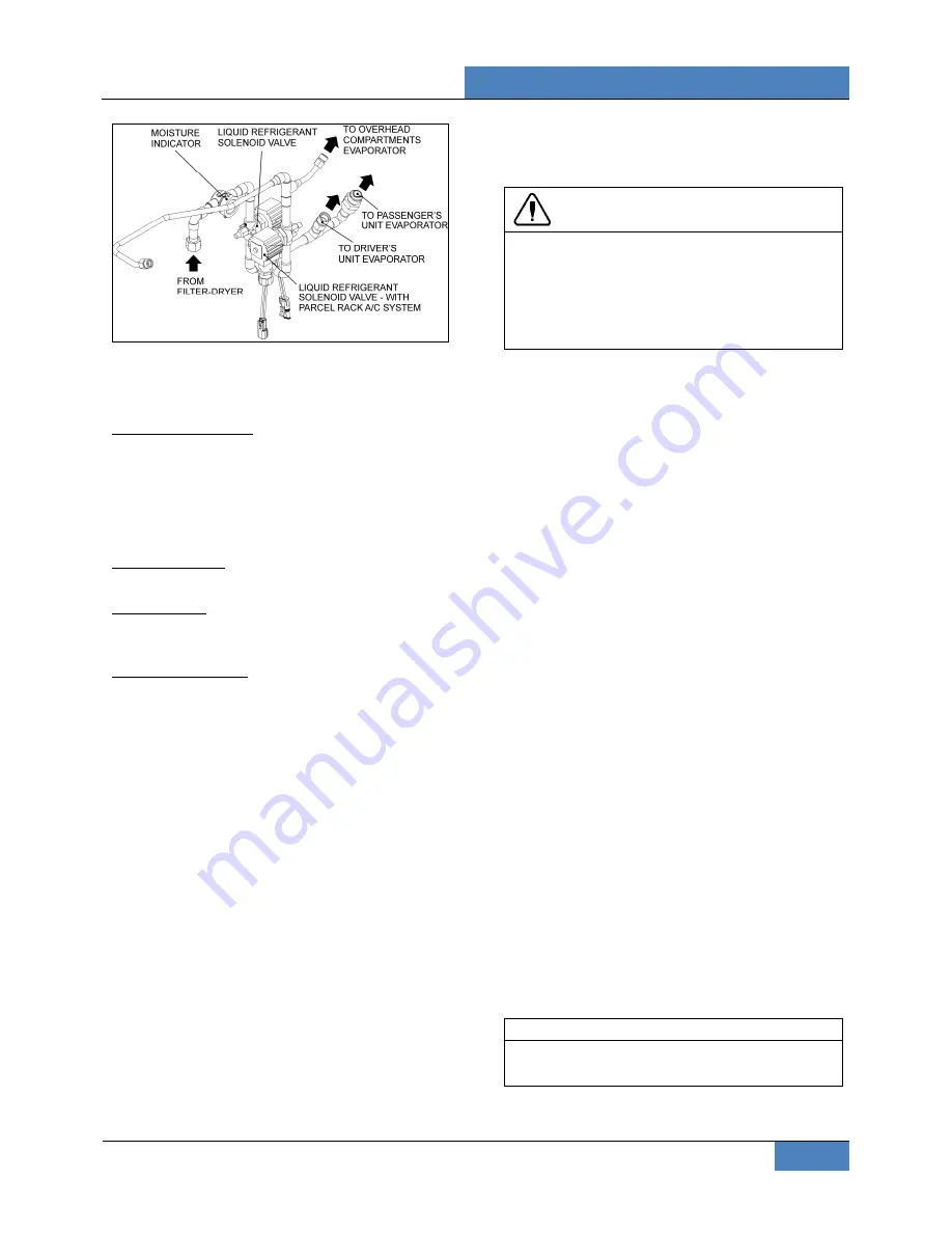
FIGURE 42: LIQUID REFRIGERANT SOLENOID VALVES
INSIDE CONDENSER COMPARTMENT
7.9.1 Typical
malfunctions
Faulty control circuit: Check the electric system
by energizing the solenoid with 24-V DC. A
metallic clicking noise indicates that the solenoid
is operating. Absence of clicking indicates a loss
of power or a defective solenoid. Check for
open breaker, open-circuited or grounded coil,
broken lead wires.
Burned-out coil: Check for open-circuited coil.
Replace coil if necessary.
Low voltage: Check voltage across the coil
leads. Voltage must be at least 85% of
nameplate rating.
Excessive leakage: Disassemble valve and
clean all parts. Replace worn or damaged parts
with a complete repair kit for best results.
There are only three main possible malfunctions:
1. Coil burnout.
2. Failure to open.
3. Failure to close.
Each is discussed in
Sporlan Parker Hannifin
Solenoid Valve Installation and Servicing
bulletin
included on your Technical Publications CD.
7.9.2 Electrical Bypass/On Demand Opening
of liquid refrigerant solenoid valves
To ease purging, pumping down and refilling of
refrigerant, it is possible to open the liquid
solenoid valves (normally closed NC). To do so,
uncap and connect plug and socket housings of
connector
C24 together for the passengers’
unit and parcel rack units liquid solenoid
valves
(located on the HVAC module in
evaporator compartment) or
C44 for the
driver's unit liquid solenoid valve
(located on
the ceiling of the spare wheel compartment).
During normal use, both plug and socket
housings of connector C24 or C44 are to be kept
unplugged and capped.
CAUTION
Connectors C24 & C44 must be disconnected
and their caps reinstalled after this procedure.
Leaving them connected will keep the driver’s,
passengers’ and parcel rack liquid solenoid
valves open, and result in battery draining if
the bus remains unused for several days.
7.9.3 Coil
Replacement
1. Unplug coil connector.
2. Take out the retaining screw at the top of the
coil housing. The entire coil assembly can
then be lifted off the enclosing tube.
3. Place the new coil on the enclosing tube.
Lay data identification plate in place.
4. Insert the coil retaining screw, rotate coil
housing to proper position and tighten screw
securely.
5. Plug coil connector.
7.9.4 Valve
Disassembly
1. Because of possible damage to valve
components due to the high temperature of
soldering and brazing, it is necessary to
completely disassemble the
A & B series
valves before any heat is applied to the
valve body. For
E series
(extended copper
connections), braze into the line without
disassembly because the valve contains
extended connections. Use caution by
placing a wet cloth or chill block on the
extensions at the body to prevent excessive
overheating.
2. Remove the coil as stated previously.
3. Pump down the system as stated in this
section.
4. Remove the enclosing tube and locknut, all
internal parts, and manual lift stem
assembly.
NOTE
The previous procedure must be followed
before brazing solder-type bodies into the line.


