


Clarus 600/680 GC User’s Guide
2-5
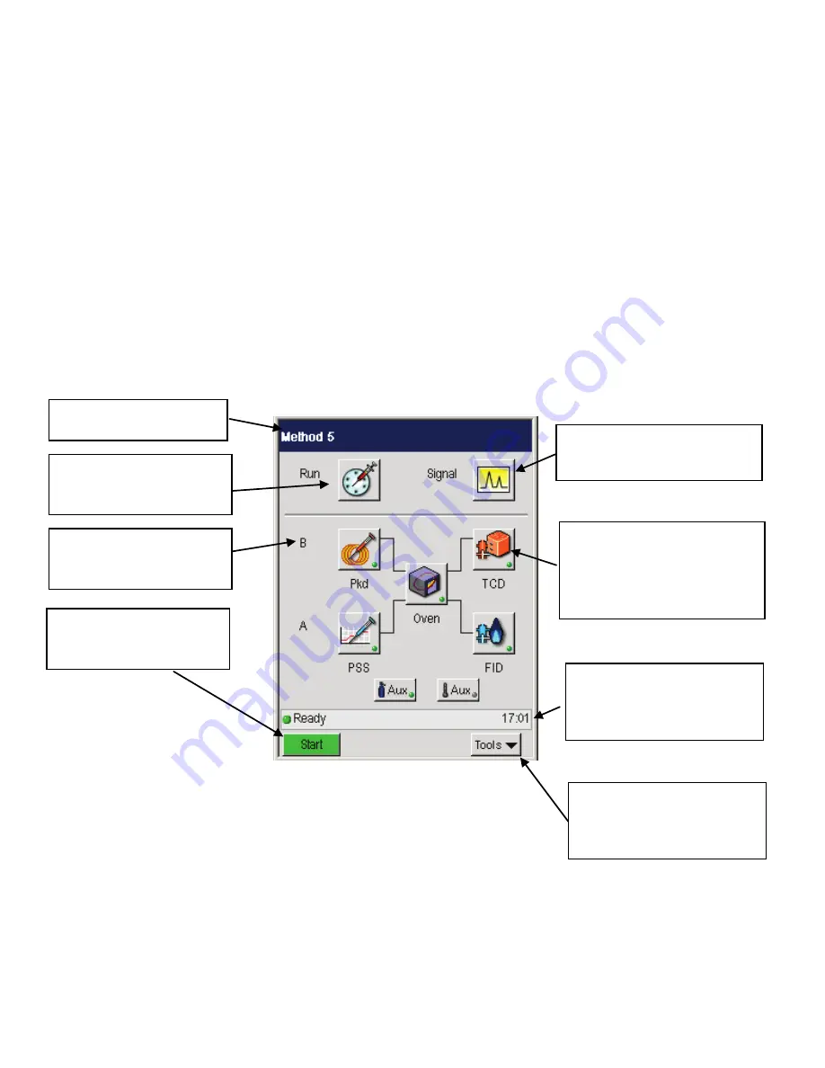
The following
Status Screen
shows the different sections of the user interface.
The Status Screen displays icons that provide quick access to major areas of the
system. The injector and detector buttons show graphic representations of the
devices for each channel. If a heated auxiliary zone is configured, the Aux button
with a thermometer appears active on the bottom of the screen. The Aux zone
button with the carrier gas icon indicates that the PPC carrier gas zone is active.
The icon buttons that represent the heated zones (injectors, detectors, oven, and
Aux if configured) include a light to indicate the ready/not ready status. A red
blinking light indicates not ready and a steady green light indicates ready status.
Click here to view the Signal. If
a method is not running the
screen will display a baseline.
The Title bar displays the
name of the active method.
The Run button provides
access to the Autosampler
and Manual Inject settings.
Channel B appears above
Channel A to emulate the
order on top of the GC.
The Icon buttons provide quick
access to all configured areas of
the instrument. An indicator
light shows the ready/not ready
status of each heated zone.
The status bar displays the
overall ready/not ready status
as well as text messages and
the real time clock/date
The bottom bar displays the
Tools pop up menu. When the
system is running the Stop
button also appears.
The Start button appears so
you can start or stop a run.
Summary of Contents for CLARUS 600 GC
Page 1: ...CLARUS 600 680 GC User s Guide GAS CHROMATOGRAPHY ...
Page 2: ......
Page 3: ...Clarus 600 680 GC User s Guide ...
Page 10: ...viii ...
Page 11: ...Introduction 1 ...
Page 12: ...Introduction 1 2 ...
Page 23: ...Touch Screen Navigation 2 ...
Page 24: ...Touch Screen Navigation 2 2 ...
Page 73: ...Using the Active Method 3 ...
Page 74: ...Using the Active Method 3 2 ...
Page 87: ...Clarus 600 680 User s Guide 3 15 The injector information displays ...
Page 119: ...Clarus 600 680 User s Guide 3 47 Setting the Timed Events 1 Touch the Events tab ...
Page 137: ...Setting Up the Detectors 4 ...
Page 138: ...Setting Up the Detectors 4 2 ...
Page 194: ...Setting Up the Detectors 4 58 2 The FPD page is now visible ...
Page 199: ...Clarus 600 680 User s Guide 4 63 4 The FPD tab page is now displayed ...
Page 230: ...Setting Up the Detectors 4 94 NOTE When Autozero is Off the output signal is never autozeroed ...
Page 231: ...Using the Method Editor 5 ...
Page 232: ...Using the Method Editor 5 2 ...
Page 248: ...Using the Method Editor 5 18 ...
Page 249: ...Using the Tools Menu 6 ...
Page 250: ...Using the Tools Menu 6 2 ...
Page 272: ...Using the Tools Menu 6 24 PID NPD ...
Page 273: ...Clarus 600 680 GC User s Guide 6 25 FPD Output Configured ...
Page 282: ...Using the Tools Menu 6 34 PPC Configure ...
Page 329: ...Setting up a Typical Analysis 7 ...
Page 330: ...Setting up a Typical Analysis 7 2 ...
Page 333: ...Clarus 600 680 GC User s Guide 7 5 ...
Page 354: ...Setting up a Typical Analysis 7 26 ...
Page 355: ...Index ...
Page 356: ...I 2 ...
Page 361: ......


