background image

4.7 Setting Running Conditions

E5EK

4--19

4.7 Setting Running Conditions

You can select from one of the following operations at power ON:

Continue, Reset, Run, Manual

If you select “Continue,” operation is started from the state that was
active when power was interrupted.

If you select “Reset,” the controller is reset.

If you select “Run,” normal program operation is started.

If you select “Manual,” the controller enters the manual mode.

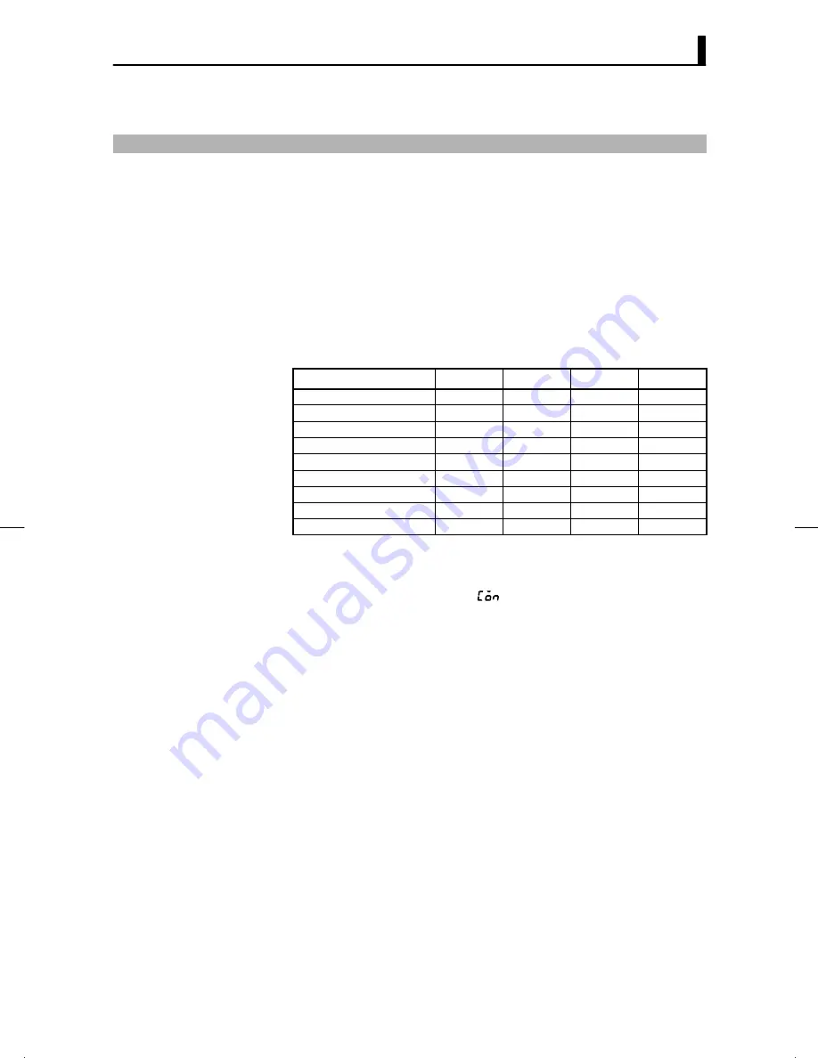
The following table shows the relationship between operation at pow-
er ON and the operation details that are stored to memory when a
power interruption occurs.

Continue

Reset

Run

Manual

Pattern No.

f

f

f

f

Step No.

f

-

-

f

Pattern elapsing time

f

-

-

f

Pattern execution count

f

-

-

f

Hold status

f

-

-

f

Auto/Manual

f

f

f

-

Run/Reset

f

-

-

f

MV at reset *1

f

-

-

f

Manual MV *2

f

f

f

f

*1 During auto mode at power interruption on a standard type controller
*2 During manual mode at power interruption on a standard type controller

Set the desired operation in the “operation at power ON” parameter
(expansion mode). Default is [

: Continue].

J

Operation at
power ON

Summary of Contents for E5EK

Page 1: ...User s Manual Cat No H089 E1 02 Digital Controller Programmable Type...

Page 2: ...e so that it can be retrieved whenever neces sary PRECAUTIONS IN USING THE PRODUCT When the product is used under the circumstances or environment below ensure adherence to limitations of the ratings...

Page 3: ...ndicated 2 _C m g and other units are indicated for scaled data However EU is used as the mini mum unit for the data For example for 50 02 m 1EU is taken as the minimum unit 0 01 m JHow to Read Displa...

Page 4: ...ctions for the E5EK T D Applied E5EK T opera tions Chapter 4 APPLIED OP ERATION Chapter 5 PARAMETERS These chapters describes the important functions of the E5EK T and how to use the pa rameters for m...

Page 5: ...for ensuring that the E5EK T is used safely The precautions indicated below describe important information regarding safety Be sure to follow the instructions described in these precautions WARNING I...

Page 6: ...ect polarity of terminals F When wiring input or output lines to your controller keep the following points in mind to reduce the influence from inductive noise Allow adequate space between the high vo...

Page 7: ...adiation use a fan to cool the surface of the controller to under 55_C F Store within the following temperature and humidity ranges Temperature 25_C to 65_C humidity 35 RH to 85 RH with no icing or co...

Page 8: ...tion 2 5 2 3 Wiring Terminals 2 8 CHAPTER 3 BASIC OPERATION 3 1 This chapter describes actual examples for understanding the basic operation of the E5EK T 3 1 Convention Used in this Chapter 3 2 3 2 S...

Page 9: ...Calibration Mode 5 52 CHAPTER 6 USING THE COMMUNICATIONS FUNCTION 6 1 This chapter mainly describes communications with a host computer and com munications commands 6 1 Outline of the Communications F...

Page 10: ...ouble in the order of the descriptions in this chapter 8 1 Initial Checks 8 2 8 2 How to Use the Error Display 8 3 8 3 How to Use the Error Output 8 5 8 4 Checking Operation Restrictions 8 6 APPENDIX...

Page 11: ...es of parts 1 2 Main parts 1 2 Front panel 1 2 About the displays 1 3 How to use keys 1 4 1 2 Input and Output 1 5 Input 1 5 Output 1 6 1 3 Program 1 8 How programs are structured 1 8 Program operatio...

Page 12: ...ls Rear case Front panel This page JFront panel OUT1 SUB1 MANU HOLD WAIT Operation indicators Run Reset key Display key Down key Up key No 2 display No 1 display E5EK PV SV OUT1 OUT2 MANU STOP RMT AT...

Page 13: ...nction assigned to control output 2 is ON SUB1 Lights when the pulse output function assigned to auxiliary output 1 is ON SUB2 Lights when the pulse output function assigned to auxiliary output 2 is O...

Page 14: ...menu display ap pears In key operations from here on press the key refers to pressing the key for less than one second For details on switching of parameters and menu display items see page 1 10 Each...

Page 15: ...of temperature input current input and voltage input can be selected and connected to the controller The following input sensors can be connected for temperature input Thermocouple K J T E L U N R S B...

Page 16: ...2 auxiliary output 1 and auxiliary output 2 However note that as control output 1 is used as the open output and control output 2 is used as close output on a position proportional type controller E5E...

Page 17: ...se The E5EK T supports the following five transfer outputs Set point Process value Heating side manipulated variable Cooling side manipulated variable Valve opening However note that heating cooling s...

Page 18: ...n parameter setup you can specify repeated execution of the same pattern Repeat or consecutive execution of all patterns 0 to 3 Run all During program operation steps can be skipped Advance and the co...

Page 19: ...change the process value step No standby time pattern elapsing time pattern execution count and manipulated variable This is the programming mode In this mode you can set the number of steps used in...

Page 20: ...ted only when the communication unit E53 AKF is set in the controller The following diagram shows the order in which modes are selected 1 second min 1 second min 1 second min 1 second min 1 second min...

Page 21: ...one second minimum with the key held down in the level 0 to 2 modes To return to the level 0 mode in the manual mode press the key for one second minimum with the key pressed Be sure to press the key...

Page 22: ...quired add on the communications unit For details on the communications function refer to Chapter 6 When using the communications function on the RS 232C interface add on the communications unit E53 A...

Page 23: ...ed with the following four calibration parameters Thermocouple Platinum resistance thermometer Current input Voltage input Two parameters are provided for thermocouple and voltage input Transfer outpu...

Page 24: ...CHAPTER 1 INTRODUCTION 1 14...

Page 25: ...nd wiring you should carry out before turning the E5EK T ON CHAPTER2 2 1 Setup 2 2 Draw out 2 2 Setting up the output unit 2 3 Setting up the option unit 2 4 2 2 Installation 2 5 Dimensions 2 5 Panel...

Page 26: ...hanism from the housing and insert the output units into the sockets for con trol outputs 1 and 2 When drawing out the internal mechanism from the housing prepare a Phillips screwdriver matched to the...

Page 27: ...ng diagram OUT2 OUT1 Bracket 2 Remove the power board in the direction of the arrow in the figure below The power board is connected to the control board by a con nector at the center of the board Pow...

Page 28: ...he relationship between units and terminals see page 2 8 1 Remove the power board and option boards in the order shown in the following diagram 1 2 2 Insert the option unit into the socket for option...

Page 29: ...B1 48 13 5 100 91 112 RUN RST 96 PTN WAIT JPanel cutout Recommended panel thickness is 1 to 8 mm Maintain the specified vertical and hori zontal mounting space between each con troller Controllers mus...

Page 30: ...ler into the mounting hole in the panel 2 Fit the mounting bracket accessory into the fixing slots on the top and bottom of the rear case 3 Tighten the two mounting bracket screws alternately a little...

Page 31: ...to protect terminals E5EK VV2 500 controller is provided with terminal covers Use E53 COV09 for terminals 1 to 10 and E53 COV08 for terminals 11 to 33 Fasten the terminal covers as follows by using t...

Page 32: ...r to protect the controller and its lines from external noise We recommend using solderless terminals when wiring the controller Tighten the terminal screws using a torque no greater than 0 78 N m 8kg...

Page 33: ...cations E53 R Relay Pulse 250 VAC 5 A E53 S SSR Pulse 75 to 250 VAC 1 A E53 Q E53 Q3 E53 Q4 Voltage NPN Voltage NPN Voltage PNP Pulse Pulse Pulse NPN 12 VDC 40 mA with short circuit protection NPN 24...

Page 34: ...Connect each of these inputs as fol lows 17 16 15 17 16 15 C W O CT CT input Potentiometer For details on CT inputs see Appendix About Current Transformer CT Input page A 5 For details on the potentio...

Page 35: ...t are as follows 20 19 18 Event input 1 and 2 EV1 EV2 COM Connect transfer output TRSF to terminal Nos 21 and 22 The internal equalizing circuit for transfer output is as follows 21 22 4 to 20mA L Tra...

Page 36: ...CHAPTER 2 PREPARATIONS 2 12...

Page 37: ...Specifications 3 7 Output assignments 3 7 Direct reverse operation 3 8 Control period 3 8 3 4 Setting Alarm Type 3 10 Alarm type 3 10 Alarm value 3 10 Alarm hysteresis 3 11 Close in alarm open in alar...

Page 38: ...ration Start Adjustment Stop Power OFF Setting patterns The descriptions in this chapter follow the order of basic operations shown in the flow above Examples of operation of each of the items are des...

Page 39: ...unit is mounted at control output 1 The upper limit alarm is set as alarm 2 The alarm is output when the temperature exceeds 10_C with respect to the PV The program is made up of one pattern comprisi...

Page 40: ...eters need not be set as this information is determined by the input sensor type These parameters are not displayed Note that temperature unit and temperature input shift parameters need to be set Wit...

Page 41: ...en the analog input the voltage input and current input is se lected scaling matched to the control is required The scaling upper limit scaling lower limit and decimal point parameters setup mode are...

Page 42: ...he key to fix the set value The display changes to _C _F selection parameter This parameter is factory set to _C 4 Select the menu display and select level 2 mode using the or keys 5 Press the key for...

Page 43: ...on assignment destination are placed on some of the out puts The following table shows where outputs may be assigned to Assignment Destination Control Output Auxiliary Output Destination Output Funct...

Page 44: ...ated variable is decreased according to the decrease in the process value For example when the process value PV temperature is lower than the set point SP temperature in a heating control system the m...

Page 45: ...output 1 assignment parameter is displayed Default is 4 As the setting in this example is to be left as it is press the key twice The display changes to auxiliary output 1 assign ment parameter Defau...

Page 46: ...d lower limit range alarm deviation ON OFF X X SP Always OFF 5 Upper and lower limit alarm with standby sequence deviation ON OFF X X SP Always OFF 6 Upper limit alarm with stand by sequence deviation...

Page 47: ...alarm setting value to leave the alarm range and once again falls below the alarm value The standby sequence is canceled when an alarm is output It is how ever restarted later by one of the following...

Page 48: ...scriptions of alarm operations when alarm type is set to lower limit alarm with standby sequence Alarm type lower limit alarm with standby sequence Alarm value Alarm Standby sequence canceled PV Alarm...

Page 49: ...value 2 set in program setting alarm hysteresis 0 02 close in alarm open in alarm close in alarm In this example let s check the alarm type 1 Select the menu display and select setup mode pressing th...

Page 50: ...ble in the program mode and the order in which they are set Select the program mode Select pattern No Set number of steps Step time Rate of rise programming Set step SP step time Set pattern execution...

Page 51: ...used in the program in order from step 0 as step 0 SP step 0 time step 1 SP step 1 time and so forth Set within the range from set point lower limit to set point upper limit for step SP Default is 0 S...

Page 52: ...e set only for alarms that have been assigned as output When a deviation alarm is assigned as output the alarm value is set with respect to SP The following example shows the relationship be tween the...

Page 53: ...steps parameter Default is 8 4 Set the parameter to 4 pressing the or keys 5 When you press the the display changes to the step 0 SP parameter Default is 0 6 Set the parameter to 50 pressing the or ke...

Page 54: ...OPERATION 3 18 12 As the setting in this example is to be left as it is set the alarm val ue Press the key until alarm 2 parameter is dis played Default is 0 13 Set the parameter to 10 10 seconds pres...

Page 55: ...not protected When this parameter is set to 5 operations in only the level 0 mode can be selected and the mode is not displayed on the menu display When this parameter is set to 6 the PV Present SP pa...

Page 56: ...controller enters the protect mode In the protect mode the top parameter in the protect mode security is displayed Default is 1 2 Press the key to change the parameter setting to 2 3 Press the key to...

Page 57: ...the RST LED lights The controller cannot be reset during auto tuning A T On a standard type controller specify the manipulated variable 5 0 to 105 0 in the MV at reset parameter level 2 mode to output...

Page 58: ...rity parameter pro tect mode is set to 5 or 6 Change the SP of steps 0 to 15 in step 0 to 15 SP parameters pro gram mode When the SP is changed midway through a step the Present SP is shifted on a lin...

Page 59: ...am mode The top parameter in the program mode pattern is displayed 5 Press the key to display the number of steps parame ter 6 Press the key step 0 SP parameter is displayed and the No 2 display indic...

Page 60: ...am operation the program ad vances When program operation is started in the manual mode pro gram also advances In the manual mode the automatic return of display mode does not work The process value i...

Page 61: ...limit cycle of MV change width to 40 select 40 AT to execute auto tuning with fluctuations in the process value kept to a minimum However note that auto tuning takes longer to execute compared with 1...

Page 62: ...a specific SP make a fixed value program as follows and execute AT AT Execution Tim ing 10 minutes 100 Step 0 Set value Step 0 100 0 10 SP Time CHAPTER 3 BASIC OPERATION 3 26 In this example let s exe...

Page 63: ...4 3 Ramp Rise Rate Setup Program 4 9 Running the ramp rise rate setup program 4 11 Program example 4 12 4 4 Program Operation 4 13 Hold Advance 4 13 Pattern operation 4 14 4 5 Wait Operation 4 16 4 6...

Page 64: ...is set with the set point as its center The dead band width is the set value of the dead band parameter level 1 mode Set ting a positive value produces a dead band while setting a negative val ue pro...

Page 65: ...ative value for the sake of convenience When the manipulated variable at reset is a negative value the manipulated variable is output to only the cooling side and when a positive value the manipulated...

Page 66: ...or calibration in the motor calibra tion parameter option mode Default is 30 30 seconds The valve opening can be monitored when a potentiometer is con nected to the controller However be sure to execu...

Page 67: ...g between ON and OFF to stabilize operation The hysteresis width provided during ON OFF control is simply referred to as hys teresis Control output heat and control output cool functions are set in th...

Page 68: ...ing and cooling control MV at reset Level 2 Manipulated variable when control operation is stopped MV at PV error Level 2 Manipulated variable when control operation is PV error Travel time Option Pos...

Page 69: ...nd cooling control the manipulated variable at the cooling side is treated as a negative value for the sake of convenience The up per limit is set for the heating side positive value and the lower lim...

Page 70: ...oint limitter if the set point is out of the limitter range Also when the input type temperature unit and scaling sensor range are changed the set point limitter is forcibly reset to the scaling senso...

Page 71: ...amming parameter expansion mode to rate of rise Target SP Step Ramp step Soak step Rate of rise Time unit of ramp rate Soak time N N 1 Set each of the above program elements in the target SP 0 to 7 ra...

Page 72: ...an be set Accordingly when the number of steps are set to an even number the final step is a soak step When it is set to an odd number the final step is a ramp step Number of steps even number Number...

Page 73: ...ime in the ramp cycle both change After change Before change Switching point Time Before change After change Step N Step N 1 Step N Step N 1 In the above figure increasing the rate of rise results in...

Page 74: ...alue 100 in step 0 If the PV is 40 when the program is started this time then becomes 20 minutes using the same formula 3 In step 1 the Present SP does not change and the step time is the value set to...

Page 75: ...arameter level 0 mode When the hold parameter level 0 mode is set to ON step time counting is paused held and the HOLD LED lights and the SP appear alternately on the No 2 display when in the PV Pres...

Page 76: ...reset or in a standby state To execute all preset patterns in order from pattern 0 set the run all enable parameter expansion mode to ON Default OFF Time Pattern 0 Pattern 1 Pattern 2 When a power in...

Page 77: ...vel 0 Advances the program one step Pattern execution count Program Repeatedly executes current pattern Run all Expansion Executes all patterns A reset cancels a hold state When the controller is rese...

Page 78: ...is smaller than SP wait width at the end of the rising step in the above figure control monitoring is stopped and the con trol waits for PV to reach SP wait width before the step is up dated In the ca...

Page 79: ...ime There are two timers for time signals ON time timer and OFF time timer These times are counted from the beginning of the step Output is ON from the ON time elapsed point up to the OFF time elapsed...

Page 80: ...se signal is output at the beginning of each step Stage output Time 1s Symbol Parameter Name Mode Description Time signal set step Program Time signal Time signal ON time Program Time signal Time sign...

Page 81: ...following table shows the relationship between operation at pow er ON and the operation details that are stored to memory when a power interruption occurs Continue Reset Run Manual Pattern No f f f f...

Page 82: ...ode within the range 0 00 to 99 59 hours minutes Defaults is 0 00 After end of operation the controller normally is reset However con trol can be continued on the SP of the final step by setting the e...

Page 83: ...reset input program operation is stopped reset at the rising OFF ON edge of the input signal and program operation is started run at the falling ON OFF edge Other signals are accepted at all times Set...

Page 84: ...ld when the event input is ON and the HOLD LED lights Holds continue until the state of the event input changes to OFF This function is enabled only during program operation Program steps are advanced...

Page 85: ...disabled When the HBA latch function is set to ON the heater burnout alarm is held until either of the following measures is taken a Set the heater burnout set value to 0 0A default b Reset the contr...

Page 86: ...the heat ers burns out with all heaters at the same current Make sure that the following condition is satisfied Heater of current 10 0 A or less Current value at normal operation current value at heat...

Page 87: ...ormal operation 1000 200 3 15A 10A Current at burnout of one heater 1000 200 2 10A 15 10 2 12 5A current at normal operation current at heater burnout 15 10 5A 2 5A Symbol Parameter Name Mode Descript...

Page 88: ...tes considerably due to the control characteristics The LBA detection width is provided so that changes with respect to output can be correctly detected Changes smaller than the detection width due to...

Page 89: ...for the input change width to reach the LBA detection width factory setting 0 2 FS PV 0 2 FS Measurement time Tm LBA detection time Tm x 2 Output Time 3 Take a value twice that of the measurement time...

Page 90: ...ed according to the settings of the transfer output upper limit and transfer output lower limit pa rameters before output Setting of an upper limit value smaller than the lower limit value is allowed...

Page 91: ...ers of the E5EK T Use this chapter as a reference guide CHAPTER5 Conventions Used in this Chapter 5 2 Protect Mode 5 3 Manual Mode 5 5 Level 0 Mode 5 6 Program Mode 5 11 Level 1 Mode 5 17 Level 2 Mode...

Page 92: ...that can be used are displayed These parameters are displayed only when the Conditions of Use on the right of the parameter heading are satisfied However note that the settings of protected parameter...

Page 93: ...be protected Only the modes indicated by the F mark in the table below can be selected on the menu display For example when this parameter is set to 3 only levels 0 and 1 and the program mode can be...

Page 94: ...ion manual operation is no longer possible The following table shows the relationship between set values and protected keys Set value Description 1 No keys are protected 2 AUTO MANUAL key operation ca...

Page 95: ...or keys the manipulated variable is changed On a position proportional type controller when you press the key the open side becomes ON and when you press the key the close side becomes ON On standard...

Page 96: ...rameter Name Page PV Present SP 5 6 Pattern No 5 7 Step No monitor 5 7 Hold 5 8 Advance 5 8 Standby time monitor 5 9 Pattern elapsing time 5 9 Pattern execution count monitor 5 9 MV monitor heat 5 10...

Page 97: ...ge Unit Default 0 to 3 None 0 F Related description 3 5 Setting Patterns page 3 14 F Related parameters All parameters in the program mode Step No monitor Monitors the current step No This parameter i...

Page 98: ...nt 1 to 2 option mode Advance This parameter can only be used for monitoring when the controller is reset Forcibly advances program operation by one step When the event input to which hold hold cancel...

Page 99: ...pattern When a pattern is repeatedly executed or all patterns are executed the time counting restarts at the top of each pattern Monitor Range Unit 0 00 to 99 59 Program time unit When the time exceed...

Page 100: ...ooling control MV monitor heat Control Monitor Range Unit Standard 5 0 to 105 0 Heating and cooling 0 0 to 105 0 MV monitor cool Control Monitor Range Unit Heating and cooling 0 0 to 105 0 E5EK TAA2 V...

Page 101: ...s supported in this mode and the page where the parameter is described Symbol Parameter Name Page Pattern No 5 7 1 Number of steps 5 12 Step 0 SP or Target SP 0 5 12 Ramp rate 0 5 13 Step 0 time or So...

Page 102: ...t Sets target SP 0 to 7 when the rate of rise programming is set During temperature input the decimal point position is dependent on the cur rently selected sensor and during analog input on the resul...

Page 103: ...ime Step time Soak time 0 Rate of rise programming to Step 7 time Step time Soak time 7 Rate of rise programming Step 8 time Step time Step 15 time Step time Sets the time of steps 0 to 15 when the st...

Page 104: ...is parameter is used for monitoring or setting the alarm values of alarm out puts 1 to 3 During temperature input the decimal point position is dependent on the cur rently selected sensor and during a...

Page 105: ...gnal 2 ON time Time signal 2 OFF time program mode Time signal 1 ON time Time signal 2 ON time Conditions of Use Each of the time signals must be assigned as outputs Sets the ON time of the time signa...

Page 106: ...the OFF time of the time signal Setting Range Unit Default 0 00 to 99 59 Program time unit 0 00 F Related description 4 6 Program output page 4 17 F Related parameters Time signal 1 enabled step Time...

Page 107: ...r 1 second mini mum the controller enters the level 1 mode To select parameters in this mode press the key To change parameter set tings use the or keys The following table shows the parameters suppor...

Page 108: ...s not displayed When AT execution ends the parameter setting automatically returns to F Related description 3 8 Adjusting Control Operation AT page 3 25 F Related parameters Proportional band Integral...

Page 109: ...ing the Control Method Heating and cooling control page 4 2 F Related parameter Proportional band level 1 mode E5EK TAA2 Dead band Conditions of Use The control system must be heating and cooling cont...

Page 110: ...1 Selecting the Control Method Position proportional control page 4 3 F Related parameter Open close hysteresis level 2 mode E5EK TPRR2 Manual reset value Conditions of Use The control must be either...

Page 111: ...et independently for heating and cooling Use the hysteresis heat parameter to set the heating side hysteresis and use the hysteresis cool parameter to set the cooling side hysteresis Parameter Setting...

Page 112: ...rameter The con trol period cool parameter cannot be used In a heating and cooling control system the control period can be set indepen dently for heating and cooling Use the control period heat param...

Page 113: ...level 1 mode HBA latch option mode E5EK TAA2 Heater burnout Conditions of Use The HBA output function must be assigned as the output Outputs the heater burnout alarm when the heater current value fall...

Page 114: ...display If you select pressing the and keys and then press the key for 1 second minimum the controller enters the level 2 mode To select parameters in this mode press the key To change parameter set...

Page 115: ...ted description Chapter 6 Using the Communications Functions F Related parameters Communication stop bit Communication data length Communication par ity Communication baud rate Communication unit No E...

Page 116: ...ror Conditions of Use Advanced PID control The MV at reset parameter sets the manipulated variable when operation has stopped on a standard type controller On a position proportional type controller t...

Page 117: ...lue is reached while changing the value by the per second value set in this parameter This function is disabled when the set value is 0 0 MV upper limit The setting ranges during standard control and...

Page 118: ...tal filter Time constant Time Setting Range Unit Default 0 to 9999 Second 0 Open close hysteresis Conditions of Use The control must be position propor tional control Provides hysteresis at ON OFF swi...

Page 119: ...rm 2 type Alarm 3 type Alarm 1 open in alarm Alarm 2 open in alarm Alarm 3 open in alarm setup mode Alarm value 1 Alarm value 2 Alarm value 3 Program mode Input shift upper limit Input shift lower lim...

Page 120: ...ond minimum the controller enters the setup mode To select parameters in this mode press the key To change parameter set tings use the or keys The following table shows the parameters supported in thi...

Page 121: ...1500 _F 9 L2 0 0 to 400 0 _C 0 0 to 750 0 _F Thermocouple 10 U 199 9 to 400 0 _C 199 9 to 700 0 _F Thermocouple 11 N 200 to 1300 _C 300 to 2300 _F 12 R 0 to 1700 _C 0 to 3000 _F 13 S 0 to 1700 _C 0 t...

Page 122: ...arameter The decimal point parameter specifies the decimal point position of parameters alarm value etc whose unit is set to EU Engineering Unit Scaling upper limit Scaling lower limit Parameter Setti...

Page 123: ..._F F Related description 3 2 Setting Input Specifications page 3 4 F Related parameter Input type setup mode Parameter initialize Returns parameter settings to their factory settings However note that...

Page 124: ...ver note that the OUT1 or OUT2 LEDs do not light if the output unit is E53 CVV or E53 VVV when control output heat or control output cool functions are assigned to control outputs Symbol to Function C...

Page 125: ...auxiliary output 1 or auxiliary output 2 is ON the SUB1 or SUB2 LED lights Symbol to to Function Alarms 1 to 3 HBA LBA Time signals 1 to 2 Symbol Function Program end Stage output Error 1 Error 2 Def...

Page 126: ...m 3 Lower limit alarm 9 Absolute value lower limit alarm 4 Upper and lower limit range alarm 10 Absolute value upper limit alarm with standby sequence 5 Upper and lower limit alarm with standby sequen...

Page 127: ...Default Close in alarm Open in alarm F Related description 3 4 Setting Alarm Type page 3 10 F Related parameters Alarm value 1 Alarm value 2 Alarm value 3 level 1 mode Alarm 1 hysteresis Alarm 2 hyste...

Page 128: ...using the and keys and then press the key for 1 second minimum the controller enters the expansion mode To select parameters in this mode press the key To change parameter set tings use the or keys Th...

Page 129: ...ults of scaling Parameter Setting Range Unit Default Set point upper limit Set point lower limit 1 to scaling upper limit EU 1300 Set point lower limit Scaling lower limit to set point upper limit 1 E...

Page 130: ...g Running Conditions Operation at power ON page 4 14 End condition Specifies a reset state or continued control on the SP of the final step after pro gram operation ends The program end state will not...

Page 131: ...1 mode Steps 0 to 15 time Soak time 0 to 7 Time signal 1 ON time Time signal 2 ON time Time signal 1 OFF time Time signal 2 OFF time program mode Step time Rate of rise programming Specifies the progr...

Page 132: ...art of program operation PV Process value at start of program operation PV start SP SP of step 0 normal program operation When PV is selected program operation is started from the position where the c...

Page 133: ...n page 4 16 Alarm during ramp step enable To enable alarms during the ramp step set to ON To disable alarm set to OFF Setting Range Default Run all enable To successively execute the program of all pa...

Page 134: ...ID con trol Normally use the default value Sets the gain when adjusting the PID parameters by auto tuning To give priority to response decrease the set value of this parameter To give priority to stab...

Page 135: ...se The control must be advanced PID con trol Normally use the factory setting The levels of limit cycle operations during AT execution are given hysteresis at event ON OFF switching This parameter set...

Page 136: ...lay changes to the menu display If you select using the and keys and then press the key for 1 second minimum the controller enters the option mode To select parameters in this mode press the key To ch...

Page 137: ...ogram runs at the falling edge ON OFF Other signals are accepted as during regular operation Settings Function Event input disabled OFF ON Reset ON OFF Run ON Manual OFF Auto ON Hold OFF Hold cancel O...

Page 138: ...5EK T controllers to the host computer set unit Nos that will not conflict with the unit Nos of other controllers Communication stop bit parameter Setting Range Unit Default 1 2 Bits 2 Communication d...

Page 139: ...ransfer output The setting range varies according to this output data Also a lower limit value larger than the upper limit value may be set Using temperature input the decimal point position of the pr...

Page 140: ...ssignments 2 setup mode E5EK TAA2 Motor calibration Conditions of Use The control must be position proportion control Executes motor calibration Be sure to execute this parameter when monitoring the v...

Page 141: ...ibration option mode E5EK TPRR2 PV dead band Conditions of Use The control must be position proportion control Sets a band centered at SP within which valve will not move Set point Process value PV de...

Page 142: ...tputs Only parameters relating to input types specified in the input type parameter setup mode can be used Also related output parameters can be used only when the communications unit E53 AKF is added...

Page 143: ...cedure 6 2 Interface 6 2 6 2 Preparing for Communications 6 3 Cable connections 6 3 Setting the communications specifications 6 4 6 3 Command Structure 6 5 6 4 Commands and Responses 6 7 Reading writi...

Page 144: ...ditions are as follows depending on the setting level Setting level 1 No restrictions Setting level 0 Writing of parameters in the setup expansion and option modes only is prohibited The remote local...

Page 145: ...5 Female DTE 9 pins 1 1 or 1 N connections are allowed In a 1 N connection up to 32 con trollers including the host computer can be connected The total cable length should not exceed 500 meters Use sh...

Page 146: ...communications specifications of the host computer and E5EK T controller When two or more controllers are connected to the host computer make sure that the communications specifications of all contro...

Page 147: ...inations specify the desired destination using unit No Command type Code Command type 1 Parameter read 2 Parameter write 3 Special command 4 Program parameter read 5 Program parameter write Command co...

Page 148: ...ting to FCS Calculate the exclusive OR from the start character to the data section The fol lowing describes an example of how to calculate the FCS for 001000000 How to Calculate FCS 1 Convert the ASC...

Page 149: ...F015 JReading writing parameters F Reading parameters Command Parameter No Parameter No Unit No FCS CR Unit No Read data FCS CR End code 2B 2B 4B 2B 2B 2B 2B 4B 2B 2B 2B 1 0 0 0 0 1 Response F Writing...

Page 150: ...monitor 1 0 0 to 55 0 18 Heater burnout alarm 0 0 to 50 0 46 LBA detection time 0 to 9999 47 MV at reset 6 5 0 to 105 0 48 MV at PV error 6 5 0 to 105 0 50 MV upper limit 3 MV lower limit 0 1 to 105 0...

Page 151: ...sed in alarm 1 Open in alarm 71 Direct Reverse operation 0 Reverse operation 1 Direct operation 28 Set point upper limit 1 Set point lower limit 1 to scaling upper limit 27 Set point lower limit 1 Sca...

Page 152: ...s command Also commu nications with the E5EK T cannot be carried out for five seconds after reset Status Monitors the status of the E5EK T Two command groups are avail able A and B depending on the in...

Page 153: ...er error ON OFF 10 11 Time signal 1 output ON OFF 2 12 Time signal 2 output ON OFF 2 13 Ramp soak Ramp Soak 14 Program end ON OFF 6 15 During standby ON OFF 1 Always OFF at linear output 2 Always OFF...

Page 154: ...riting parameters Parameter No Parameter No Unit No Write data FCS CR Unit No Write data FCS CR End code 2B 2B 4B 2B 2B 2B 2B 4B 2B 2B 2B 5 5 Command Response Parameters relating to the program of the...

Page 155: ...SP 4 SP lower limit to SP upper limit 18 Ramp rate 4 0 to 9999 19 Step 4 time Soak time 4 0 00 to 99 59 20 Step 5 SP Target SP 5 SP lower limit to SP upper limit 21 Ramp rate 5 0 to 9999 22 Step 5 ti...

Page 156: ...l 1 OFF time 0 00 to 99 59 48 Time signal 2 enabled step 0 to 15 49 Time signal 2 ON time 0 00 to 99 59 50 Time signal 2 OFF time 0 00 to 99 59 62 Standby time 0 00 to 99 59 Level 2 54 Operation at po...

Page 157: ...ntrol An attempt was made to switch run reset in setting level 1 An attempt was made to execute AT in setting level 1 Issue the parameter read or write commands in conditions other than above End code...

Page 158: ...le cause is a problem in the communications circuit of one or both of the host computer and E5EK T controller End code 15 Code name Setting range error Numerical values or code values in the data are...

Page 159: ...atically generated The output format is as follows The content of the response frame is displayed as it is Unit No Command code Data FCS Command type CR End code 2B 1B 2B 4B 2B 2B 2B F Procedure 1 Rea...

Page 160: ...LEN SEND 1140 FCS FCS XOR ASC MID SEND IFCS 1 1150 NEXT 1160 FCS RIGHT 0 HEX FCS 2 1170 Execute communications 1180 ZZZ SEND FCS CHR 13 1190 PRINT 1 ZZZ 1120 Check response 1210 RECCNT 0 TMP 1220 DREC...

Page 161: ...so response are displayed without spaces between frame items F Set the set point to 300 0 Input data 00 5 05 3000 300 0 Set point Write parameter Response 00 5 05 00 3000 FCS Normal end F Start runnin...

Page 162: ...CHAPTER 6 USING THE COMMUNICATIONS FUNCTION 6 20...

Page 163: ...operation Read this chapter only when the controller must be calibrated CHAPTER7 7 1 Parameter Structure 7 2 7 2 Calibrating Thermocouples 7 4 7 3 Calibrating Platinum Resistance Thermometers 7 7 7 4...

Page 164: ...fer output function is sup ported To select the desired parameter press the key Parameters are displayed in the following order Calibration of inputs Calibration of transfer output Storage of calibrat...

Page 165: ...sensor error causes the process value to stray from the calibration target range When the process value display is flashing the process value is not stored as data even if the key is pressed Once the...

Page 166: ...rce and DMM refers to a precision digital multimeter However note that DMM is required only when the transfer output function is supported Use the compensating conductor on the selected thermocouple H...

Page 167: ...as compensation value Disconnect the STV and enable the thermocouple of the cold junction compensator When carrying this out make sure that the wiring on the STV is disconnected Make sure that the col...

Page 168: ...compensation value Disconnect the STV and enable the thermocouple of the cold junction compensator When carrying this out make sure that the wiring on the STV is disconnected Make sure that the cold j...

Page 169: ...orted skips steps 7 to 10 1 When is displayed the 30 minute timer is displayed on the No 2 display and counts down This timer serves as a guide for the aging time when aging is required 2 First calibr...

Page 170: ...le monitoring the voltage on the digital multimeter In the example on the left the display indicates that the value two digits smaller than before calibration is 20 mA 9 Press the key The display chan...

Page 171: ...libra tion display Set the STV output to 0 mA When the value on the No 2 display has stabilized changes of several digits max press the key to temporarily store the calibration data 4 Next calibrate t...

Page 172: ...display has stabilized changes of several digits max press the key to temporarily store the calibration data 3 Press the key The display changes to 0 V calibration display Set the STV output to 0 V Wh...

Page 173: ...display Set the STV output to 0 V When the value on the No 2 display has stabilized changes of several digits max press the key to temporarily store the calibration data 4 Next calibrate the transfer...

Page 174: ...sator are con nected by a compensating conductor for the input type thermocou ple that is to be used during actual operation 10 9 8 7 6 5 4 3 2 1 20 19 18 17 16 15 14 13 12 11 21 22 23 STV Cold juncti...

Page 175: ...STV AC100 240V AC DC24V SOURCE Operation Set the STV to the current value equivalent to the check value Preparation The following figure show the required device connection 10 9 8 7 6 5 4 3 2 1 20 19...

Page 176: ...CHAPTER 7 CALIBRATION 7 14...

Page 177: ...ind out and remedy the cause if the E5EK T does not function properly Remedy E5EK T trouble in the order of the descriptions in this chap ter CHAPTER8 8 1 Initial Checks 8 2 8 2 How to Use the Error D...

Page 178: ...are properly connected 3 Communications conditions When communicating via the RS 232C RS 422 or RS 485 inter faces make sure that the baud rate and other communications condition settings on the host...

Page 179: ...isplay remains the same the E5EK T controller must be repaired If the display is re stored to normal then a probable cause can be external noise affecting the control system Check for external noise C...

Page 180: ...layed when the process value exceeds the display range when the control range setting range 10 is larg er than the display range 1999 to 9999 When less than 1999 When greater than 9999 Control continu...

Page 181: ...ed transistors etc 3 Sensor error constant input values etc If you use the LBA function set the loop break detection time matched to the control characteristics in the LBA detection time parameter lev...

Page 182: ...operating conditions violate the restrictions in this table Restriction Inoperable or Invalid Functions Restriction AT Execution Limitter Function Other At heating and cooling control 40 AT At positi...

Page 183: ...APPENDIX A 1 APPENDIX SPECIFICATIONS A 2 ABOUT CURRENT TRANSFORMER CT A 5 CONTROL BLOCK DIAGRAM A 6 SETTING LIST A 8 MODEL LIST A 11 PARAMETER OPERATIONS LIST A 12 ASCII CODE LIST A 14...

Page 184: ...output unit see Output Unit Ratings and Characteristics page A 4 Auxiliary Output SPST NO 3 A at 250 VAC resistive load Control Method Advanced PID or ON OFF control Setting Method Digital setting usi...

Page 185: ...d Z directions Vibration Resistance Destruction 10 to 55 Hz 10m s2 approx 2G for 2 hrs each in X Y and Z directions Shock Resistance Malfunction 200 m s2 min approx 20G 3 times each in 6 directions 10...

Page 186: ...F 170 to 1870 C 300 to 3300 F B 100 to 1800 C 300 to 3200 F 170 to 1870 C 300 to 3300 F W 0 to 2300 C 0 to 4100 F 70 to 1970 C 10 to 3490 F PL 0 to 1300 C 0 to 2300 F 230 to 2530 C 410 to 4510 F 4 to...

Page 187: ...nuous heater current 50A 120A 1 Dielectric Strength 1000 VAC 1 min Vibration Resistance 50 Hz 98 m s2 10G Weight Approx 11 5g Approx 50g Accessory Armature 2 Plug 2 1 The maximum continuous current of...

Page 188: ...de Control mode ON OFF control PID control ON OFF control 3 position control PID control MV change rate limitter MV change rate limitter MV limitter MV limitter Dead band MV at PV error Manual MV MV a...

Page 189: ...t Analog input Digital filter Scaling Input type PID control Position propor tional dead band Error Stop Manual Error Stop Manual Process function Control Data Digital filter MV changer rate limitter...

Page 190: ...0 to 15 None 0 Time signal 1 ON time 0 00 to 99 59 4 0 00 Time signal 1 OFF time 0 00 to 99 59 4 0 00 Time signal 2 enabled step 0 to 15 None 0 Time signal 2 ON time 0 00 to 99 59 4 0 00 Time signal...

Page 191: ...Analog input _C _F selection _C _F None _C Temperature input Parameter initialize Yes No None NO Control output 1 assignment 7 None HEAT Control output 2 assignment 7 None AL 1 Auxiliary output 1 assi...

Page 192: ...ignment 2 NON RST MAN HOLD ADV PTN0 to 2 None NON Communication stop bit 1 2 bit 2 Communication data length 7 8 bit 7 Communication parity NONE EVEN ODD None EVEN Communication baud rate 1 2 2 4 4 8...

Page 193: ...SETTING LIST A 11...

Page 194: ...proportional model with terminal cover E5EK TPRR2 AC DC24 Position proportional model E5EK TPRR2 500 AC DC24 Position proportional model with terminal cover Option unit E53 AKB Event input E53 AK01 Co...

Page 195: ...ond min 1 second min RUN RST RUN RST RUN RST Level 0 Program Level 1 PV Present SP Pattern No AT Execute Cancel Pattern No Number of steps Proportional band Step No monitor Step 0 to 7 SP Integral tim...

Page 196: ...arm during ramp step enable Alarm 2 hysteresis Alarm 1 open in alarm Run all enable Alarm 3 hysteresis Alarm 2 type Input shift upper limit Alarm 2 open in alarm AT calculated gain Input shift lower l...

Page 197: ...0101 0110 0111 0 0000 SP 0 P p 1 0001 1 A Q a q 2 0010 2 B R b r 3 0011 3 C S c s 4 0100 4 D T d t 5 0101 5 E U e u 6 0110 6 F V f v 7 0111 7 G W g w 8 1000 8 H X h x 9 1001 9 I Y i y A 1010 J Z j z B...

Page 198: ...ing A T 3 25 Auto turning key 1 4 Auto Manual 4 22 Auxiliary output 2 10 Auxiliary output 1 assignment 5 35 Auxiliary output 2 assignment 5 35 B B group 6 11 Balance less Bump less Operation 3 24 Basi...

Page 199: ...23 Heating and cooling control 4 2 Hold 5 8 Hold advance 4 13 Hold Hold cancel 4 22 How the program works 4 12 How to Calculate FCS 6 6 How to calculate the heater burnout set value 4 24 How to Read...

Page 200: ...14 Pattern execution count monitor 5 9 Pattern No 1 3 3 15 5 7 Pattern operation 4 14 Pattern select 4 22 PID ON OFF 5 39 Platinum resistance thermometer 7 12 Position proportional control 4 4 Positi...

Page 201: ...0 time Step time 5 12 5 13 Step 15 SP Step time 5 12 Step 15 time Step time 5 13 Step 7 SP Step time 5 12 Step 7 time Step time 5 13 Step 8 SP Step time 5 12 Step 8 time Step time 5 13 Step No monitor...

Page 202: ...e following table outlines the changes made to the manual during each revision Page numbers refer to previous version Revision code Date Revised content 1 September 1997 Original production 01A March...

Page 203: ...3 5302 U S A Tel 1 847 843 7900 Fax 1 847 843 7787 Regional Headquarters OMRON EUROPE B V Wegalaan 67 69 2132 JD Hoofddorp The Netherlands Tel 31 2356 81 300 Fax 31 2356 81 388 Contact www ia omron co...

Reviews: