


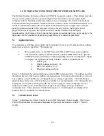


5.0 INTERFACING USING THE REMOTE INTERFACE SOFTWARE
The Remote Interface Software is shipped with XR Series power supplies. The software provides
the user with a quick method to operate a Magna-Power Electronics’ power supply under
computer control. The Remote Interface Software has six windows: the Virtual Control Panel,
Command Panel, Register Panel, Calibration Panel, Firmware Panel, and Modulation Panel. The
Virtual Control Panel emulates the front panel of the XR Series power supply, the Command
panel programs and reads SCPI commands with user friendly buttons, the Register Panel
programs and reads registers, the Calibration Panel enables calibration of the digital
potentiometers, the Firmware Panel enables the program stored internal to the power supply to be
upgraded, and the Modulation Panel eases programming of modulation parameters.
5.1
Application Setup
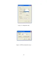
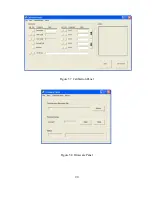
To communicate with the power supply, the front panel version, type of communication, address
and/or port need to be specified. The options are:
1.
Power supply series: select XR Version for XR or XRC Series power supplies,
2.
Communications interface: RS232, RS485, optional GPIB (IEEE-488), optional
TCP/IP (Ethernet), simulated, or others depending on future developments. Figure
5.1 displays the Applications Setup Window. Address requirements are:
a.
RS232: port.
b.
RS485: address and port, 1-30.
c.
IEEE-488: address, 1-30.
d.
Ethernet: address and port.
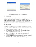
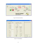
Figure 5.2 illustrates the communications setup for GPIB communications. The address specifies
the desired device on the bus to establish communications. To locate a particular device or to set
a new address, press Find Device or Change Device’s setting, respectively. The Find Devices
panel displays all devices on the bus that are available for communications. The Change Device’s
Setting allows the address of the particular device to be changed. When changing a device’s
address, the address in the Communication Setup will also change allowing continued
communications. These panels are illustrated in figure 5.3. Similar panels are displayed for
Ethernet, RS232, and RS485 communications.
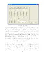
5.2
Virtual Control Panel
Figure 5.4 illustrates the Virtual Control Panel for XR Panel and C Panel models. The Virtual
Control Panel emulates front panel commands and provides the means to control C Version
models.
84
Summary of Contents for XR III series
Page 1: ...OPERATING AND SERVICE MANUAL XR SERIES III DC POWER SUPPLIES...
Page 2: ......
Page 3: ...MAGNA POWER ELECTRONICS INC 39 ROYAL ROAD FLEMINGTON NJ 08822 February 20 2012...
Page 4: ......
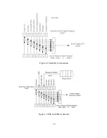
Page 88: ...Figure 4 1 Status Byte Generation Figure 4 2 ESE and ESR Generation 76...
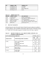
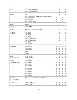
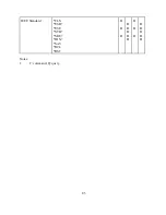
Page 95: ...IEEE Standard CLS ESR ESE STB SRE IDN SAV RCL RST Notes 1 C command Q query 83...
Page 97: ...Figure 5 1 Configuration setup Figure 5 2 GPIB communications setup 85...
Page 99: ...Figure 5 4 Virtual Control Panel Figure 5 5 Command Panel 87...
Page 102: ...Figure 5 7 Calibration Panel Figure 5 8 Firmware Panel 90...
Page 103: ...Figure 5 9 Modulation Panel 91...
Page 123: ...Figure B 1 Information Panel Figure B 2 Configure Panel 111...
Page 124: ...Figure B 3 Reboot in Progress Panel Figure B 4 Web Control Panel 112...


