


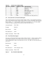
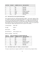

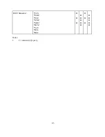


Table 4.6
EVENT STATUS REGISTER
BIT POS. WEIGHT
ABBREVIATION
DESCRIPTION
0
1
OPC
Operation Complete
1
2
NU
Not Used
2
4
QYE
Query Error
3
8
DDE
Device Dependent Error
4
16
EXE
Execution Error
5
32
CME
Command Error
6
64
NU
Not Used
7
128
PON
Power On Event, 1 after power on
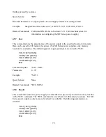
4.5.3 Read and Set Event Status Enable Register
This command programs the Event Status Enable Register (ESE). The programming determines
which events of the Event Status Register (ESR) set the Event Status Bit (ESB) of the Status Byte
Register (STB). A "1" in the bit position enables the corresponding event. All of the enabled
events of the ESE are logically OR’d to cause the ESB of the STB to be set.
Command Syntax:
*ESE <NR1>
Example:
*ESE 255
Query Syntax:
*ESE?
Return Parameter:
<NR1>
Related Commands: *ESR?, *STB?
4.5.4 Read Status Byte Register
This query reads the Status Byte Register (STB), defined in Table 4.7, which contains the Master
Status Summary (MSS) bit, Event Status (ESB) bit, and the Message Available (MAV) bit.
Unlike reading ESR, the STB is not cleared after it is read. The MAV bit is cleared at power on
or by *CLS.
Query Syntax:
*STB?
Example:
*STB?
Return Parameter:
<NR1> (Register value)
Related Commands: *ESR?, *ESE
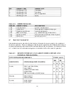
Table 4.7
STATUS BYTE REGISTER
77
Summary of Contents for XR III series
Page 1: ...OPERATING AND SERVICE MANUAL XR SERIES III DC POWER SUPPLIES...
Page 2: ......
Page 3: ...MAGNA POWER ELECTRONICS INC 39 ROYAL ROAD FLEMINGTON NJ 08822 February 20 2012...
Page 4: ......
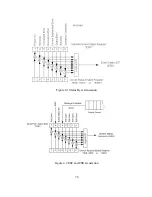
Page 88: ...Figure 4 1 Status Byte Generation Figure 4 2 ESE and ESR Generation 76...
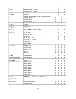
Page 95: ...IEEE Standard CLS ESR ESE STB SRE IDN SAV RCL RST Notes 1 C command Q query 83...
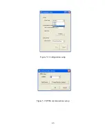
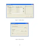
Page 97: ...Figure 5 1 Configuration setup Figure 5 2 GPIB communications setup 85...
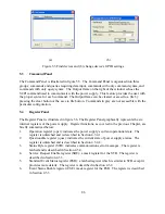
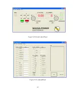
Page 99: ...Figure 5 4 Virtual Control Panel Figure 5 5 Command Panel 87...
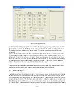
Page 102: ...Figure 5 7 Calibration Panel Figure 5 8 Firmware Panel 90...
Page 103: ...Figure 5 9 Modulation Panel 91...
Page 123: ...Figure B 1 Information Panel Figure B 2 Configure Panel 111...
Page 124: ...Figure B 3 Reboot in Progress Panel Figure B 4 Web Control Panel 112...


