


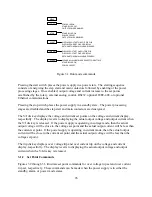


ALARMS
LOC: interlock
PGL: external input beyond limits
PHL: indicates a problem with input voltage
THL: indicates over-temperature
OVT: shows over voltage protection has tripped
OCT: shows over current protection has tripped
CONFIGURATION
REM SEN: indicates remote sense
INT CTL: front panel controls enabled
EXT CTL: external controls enabled
ROTARY: potentiometer voltage/current control
EXT PGM: external voltage/current control
REMOTE: RS232 control enabled
MODE
POWER: indicates power output
STANDBY: indicates control power only
Switches main power
on and off
FUNCTION KEYS
MENU: selects function
ITEM: selects item within function
V/I DIS: displays voltage and current settings
TRIP DIS: displays OVT and OCT settings
CLEAR: clears setting or resets fault condition
ENTER: enter
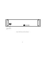
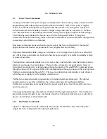
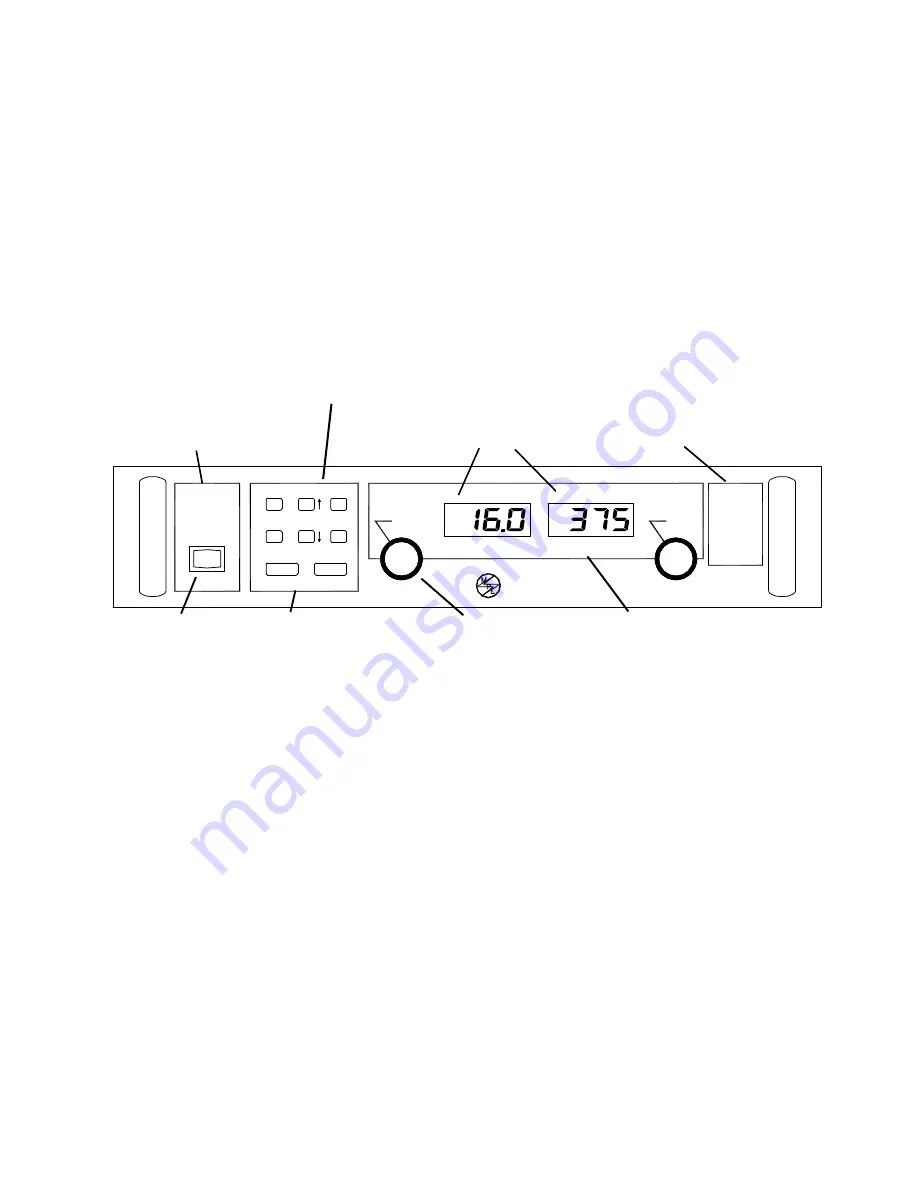
Figure 2.1 XR Series controls and indicators
OCT
OVT
THL
PHL
PGL
LOC
CTL
CTL
REM SEN
INT CTL
EXT CTL
ROTARY
EXT PGM
REMOTE
POWER
STANDBY
MENU
V/I DIS
CLEAR
ITEM
TRIP DIS
ENTER
START
STOP
CURRENT
VOLTAGE
DC VOLTAGE
DC CURRENT
CONFIGURATON
MODE
PWR
ELECTRONICS
M
AGNA-POWER
Meters display output voltage, output current,
voltage set point, current set point, over
voltage trip, and over current trip
Sets voltage and current
output
Energizes control circuits without
turning on main power
23
Summary of Contents for XR III series
Page 1: ...OPERATING AND SERVICE MANUAL XR SERIES III DC POWER SUPPLIES...
Page 2: ......
Page 3: ...MAGNA POWER ELECTRONICS INC 39 ROYAL ROAD FLEMINGTON NJ 08822 February 20 2012...
Page 4: ......
Page 88: ...Figure 4 1 Status Byte Generation Figure 4 2 ESE and ESR Generation 76...
Page 95: ...IEEE Standard CLS ESR ESE STB SRE IDN SAV RCL RST Notes 1 C command Q query 83...
Page 97: ...Figure 5 1 Configuration setup Figure 5 2 GPIB communications setup 85...
Page 99: ...Figure 5 4 Virtual Control Panel Figure 5 5 Command Panel 87...
Page 102: ...Figure 5 7 Calibration Panel Figure 5 8 Firmware Panel 90...
Page 103: ...Figure 5 9 Modulation Panel 91...
Page 123: ...Figure B 1 Information Panel Figure B 2 Configure Panel 111...
Page 124: ...Figure B 3 Reboot in Progress Panel Figure B 4 Web Control Panel 112...


