


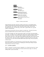


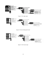


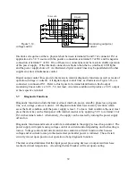
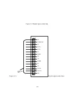

Figure 3.2 Set over voltage trip
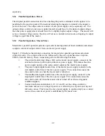
Figure 3.3 Set over current trip
With the power supply configured for rotary input, voltage and current set point commands are
entered with the front panel potentiometers and over voltage trip and over current trip are entered
with the up/down keys.
To set over voltage trip or over current trip, press the menu key. The OVT (over voltage trip)
LED will initially flash. This indicates that an up/down entry will create a new OVT set point.
Pressing the item key causes the OCT (over current trip) LED to flash indicating that an up/down
entry will create a new OCT set point. After the change is made, the enter key must be pressed
to save the new set point or the clear key can be pressed to exit without saving the new set point.
In all control modes, set point voltage and current can be quickly displayed by simply pressing
the V/I dis key. Similarly, set points for OVT and OCT can be displayed by pressing the trip dis
key.
The up/down keys have an acceleration feature to speed up entries. Pressing and holding the
OVT DISPLAY INCREMENTS
OVT DISPLAY DECREMENTS
PS RETURNS TONORMAL OPERATION
PS RETURNS TONORMAL OPERATION
OVT DISPLAY ENTERED AS OVT SET POINT
ENTER
CLEAR
CLEAR 5
OVT AND OCT LEDSFLASH
FLASHING ENTRIES SET TO FACTORY DEFAULT
PS RETURNS TONORMAL OPERATION
OVT SET POINT RETURNS TO PREVIOUS SETTING
1. CLEAR 5: CLEAR PRESSED FOR 5 SECONDS
NOTES:
2. ENTRIES LIMITED BETWEEN 10% AND 100% FULL SCALE
MENU
START
STOP
TRIP SET
CLEAR
V/I SET
conF FLASHES IN VOLT DISPLAY
(STANDBY MODE ONLY)
CAL FLASHES I N VOLT DISPLAY
OCT DISPLAYED IN CUR DISPLAY
OVT DISPLAYED IN VOLT DISPLAY
OCT LED FLASHES
OVT LED FLASHES
I TEM
OCT DISPLAY INCREMENTS
OCT DISPLAY DECREMENTS
PS RETURNS TONORMAL OPERATION
PS RETURNS TONORMAL OPERATION
OCT DISPLAY ENTERED AS OCT SET POINT
ENTER
CLEAR
CLEAR 5
OVT AND OCT LEDSFLASH
FLASHING ENTRIES SET TO FACTORY DEFAULT
PS RETURNS TONORMAL OPERATION
OCT SET POINT RETURNS TO PREVIOUS SETTING
1. CLEAR 5: CLEAR PRESSED FOR 5 SECONDS
NOTES:
2. ENTRIES LIMITED BETWEEN 10% AND 100% FULL SCALE
MENU
START
STOP
TRIP SET
CLEAR
V/I SET
conF FLASHES IN VOLT DISPLAY
(STANDBY MODE ONLY)
CAL FLASHES I N VOLT DISPLAY
OCT DISPLAYED IN CUR DISPLAY
OVT DISPLAYED IN VOLT DISPLAY
OCT LED FLASHES
OVT LED FLASHES
I TEM
27
Summary of Contents for XR III series
Page 1: ...OPERATING AND SERVICE MANUAL XR SERIES III DC POWER SUPPLIES...
Page 2: ......
Page 3: ...MAGNA POWER ELECTRONICS INC 39 ROYAL ROAD FLEMINGTON NJ 08822 February 20 2012...
Page 4: ......
Page 88: ...Figure 4 1 Status Byte Generation Figure 4 2 ESE and ESR Generation 76...
Page 95: ...IEEE Standard CLS ESR ESE STB SRE IDN SAV RCL RST Notes 1 C command Q query 83...
Page 97: ...Figure 5 1 Configuration setup Figure 5 2 GPIB communications setup 85...
Page 99: ...Figure 5 4 Virtual Control Panel Figure 5 5 Command Panel 87...
Page 102: ...Figure 5 7 Calibration Panel Figure 5 8 Firmware Panel 90...
Page 103: ...Figure 5 9 Modulation Panel 91...
Page 123: ...Figure B 1 Information Panel Figure B 2 Configure Panel 111...
Page 124: ...Figure B 3 Reboot in Progress Panel Figure B 4 Web Control Panel 112...


