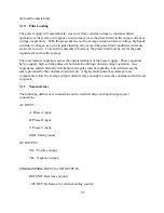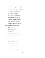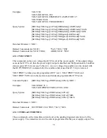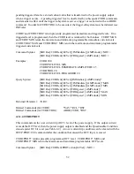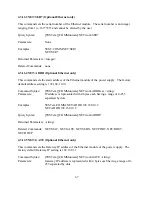
initiate continuous is enabled (INIT:CONT ON), the trigger subsystem immediately re-initiates
itself after ABORt, thereby setting WTG. ABOR is executed at power turn on and upon
execution of *RCL or *RST.
Command Syntax:
ABORt <>
Examples:
ABOR
Query Syntax:
None
Related Commands: INIT, TRIG, *RCL, *RST
4.3.7 Trigger Subsystem
This subsystem controls remote triggering of the power supply. When the trigger subsystem is
enabled, a TRIG command generates a trigger signal. The trigger signal will then initiate a
pending level change as specified by CURR[:LEV]:TRIG or VOLT[:LEV]:TRIG. Afterwards,
the Operation Register will be cleared. If INIT:CONT is on, the trigger subsystem is immediately
re-enabled for subsequent triggers. As soon as it is cleared, the WTG bit is again set to 1.
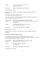
Command Syntax:
TRIGger[:IMMediate] <>
Examples: TRIG
TRIGGER:IMMEDIATE
Query Syntax:
None
Related Commands: ABOR, CURR:TRIG, INIT, *TRG, VOLT:TRIG
4.3.8 Initiate Subsystem
This subsystem enables the trigger system. When the initiate subsystem is enabled, a TRIG
command allows specified triggering action to occur. If the initiate subsystem is not enabled, all
trigger commands are ignored. If INIT:CONT is OFF, then INIT enables the trigger subsystem
only for a single trigger action; INIT must then be repeated prior to further trigger commands. If
INIT:CONT is ON, then the trigger subsystem is continuously enabled.
INIT:CONT? returns the state of the continuous trigger mode.
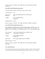
Command Syntax:
INITiate[:IMMediate] <>
INITiate:CONTinuous <bool>
Parameters (for INIT[:IMM]):
None
Parameters (for INIT:CONT):
0 | 1 | OFF | ON
59
Summary of Contents for XR III series
Page 1: ...OPERATING AND SERVICE MANUAL XR SERIES III DC POWER SUPPLIES...
Page 2: ......
Page 3: ...MAGNA POWER ELECTRONICS INC 39 ROYAL ROAD FLEMINGTON NJ 08822 February 20 2012...
Page 4: ......
Page 88: ...Figure 4 1 Status Byte Generation Figure 4 2 ESE and ESR Generation 76...
Page 95: ...IEEE Standard CLS ESR ESE STB SRE IDN SAV RCL RST Notes 1 C command Q query 83...
Page 97: ...Figure 5 1 Configuration setup Figure 5 2 GPIB communications setup 85...
Page 99: ...Figure 5 4 Virtual Control Panel Figure 5 5 Command Panel 87...
Page 102: ...Figure 5 7 Calibration Panel Figure 5 8 Firmware Panel 90...
Page 103: ...Figure 5 9 Modulation Panel 91...
Page 123: ...Figure B 1 Information Panel Figure B 2 Configure Panel 111...
Page 124: ...Figure B 3 Reboot in Progress Panel Figure B 4 Web Control Panel 112...

