


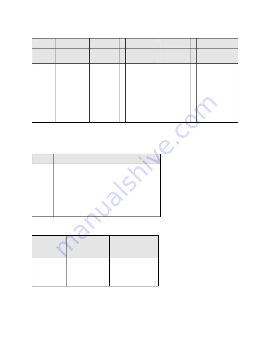
Table 1.2
MODEL ORDERING SYSTEM – Example XR500-16/208+WC+LXI
XR
D
500
- 16
/ 208
+ WC+LXI
SERIES
NAME
FRONT
PANEL
OUTPUT
VOLTAGE
OUTPUT
CURRENT
INPUT
VOLTAGE
OPTIONS
XR
PQ
TS
MS
MT
A: Analog
D: Digital
C: Computer
Blank: XR
See Tables
1.11 and
greater
See Tables
1.11 and
greater
208 SP
240 SP
208
240
380
415
440
480
See Table 1.3
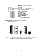
Note:
1) Multiple options can be specified as indicated.
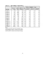
Table 1.3
OPTIONS
TERM
DEFINITION
EMI
WC
HS
LXI
GPIB
USB
RS485
EW
EMI Filter
Water Cooling
High-Slew Rate
LXI TCP/IP Ethernet Interface (Internal)
IEEE488.2 GPIB Interface (Internal)
USB Interface (External)
RS485 Interface (External)
Extended Warranty
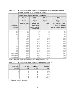
Table 1.4
SIZE AND WEIGHT MATRIX
POWER
kW
SIZE
H”xW”xD”
WEIGHT
LBS
2.0
4.0
6.0
8.0
3½x19x24
3½x19x24
3½x19x24
3½x19x24
45
47
48
48
9
Summary of Contents for XR III series
Page 1: ...OPERATING AND SERVICE MANUAL XR SERIES III DC POWER SUPPLIES...
Page 2: ......
Page 3: ...MAGNA POWER ELECTRONICS INC 39 ROYAL ROAD FLEMINGTON NJ 08822 February 20 2012...
Page 4: ......
Page 88: ...Figure 4 1 Status Byte Generation Figure 4 2 ESE and ESR Generation 76...
Page 95: ...IEEE Standard CLS ESR ESE STB SRE IDN SAV RCL RST Notes 1 C command Q query 83...
Page 97: ...Figure 5 1 Configuration setup Figure 5 2 GPIB communications setup 85...
Page 99: ...Figure 5 4 Virtual Control Panel Figure 5 5 Command Panel 87...
Page 102: ...Figure 5 7 Calibration Panel Figure 5 8 Firmware Panel 90...
Page 103: ...Figure 5 9 Modulation Panel 91...
Page 123: ...Figure B 1 Information Panel Figure B 2 Configure Panel 111...
Page 124: ...Figure B 3 Reboot in Progress Panel Figure B 4 Web Control Panel 112...


