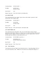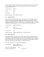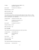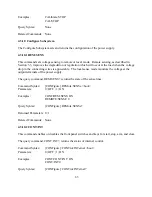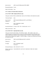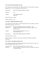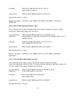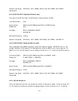
Returned Parameters: 0 | 1
Related Commands: *RST, *RCL, *SAV
4.3.5.2 OUTP:ARM (not available for XR Series power supplies)
This command selects between the modes of operation. There are two modes of operation for the
power supply: normal mode and auto sequence mode. Normal mode energizes the current
parameters of the supply until stopped. Auto sequence mode sequentially steps through the
memory updating the supply’s parameters as it increments. Each memory location contains the
voltage set point, current set point, over voltage trip, over current trip, and period. The period
parameter specifies the time period for operating at the memory location when auto sequence
operation is deployed. When enabled, the ARM light lights on the front panel.
To initiate a program sequence, select the starting memory location, execute this command, and
issue an OUPT:START (see OUTP:START) or use the front panel start switch. The ARM light
will blink after the start command. If this process reaches the upper memory limit, memory
location 99, the following memory location will revert back to 0 and continue. Auto sequence
operation will continue until an OUTP:STOP is commanded or a memory location with period set
to 0 is encountered.
ARM? returns the arm state of the power supply.
Command Syntax:
OUTP:ARM <bool>
Parameters:
0 | OFF | 1 | ON
Examples:
OUTP:ARM OFF
OUTP:ARM 1
Query Syntax:
OUTP:ARM?
Returned Parameters: 0 | 1
Related Commands: *RST, OUTP:START, OUTP:STOP
4.3.5.3 OUTP:START
This command closes the power supply’s input contactor and initiates either normal or program
mode. Auto sequence mode will be initiated if the ARM option is enabled. Normal mode
energizes the power supply with the current parameters for voltage set point, current set point,
over voltage trip, and over current trip. Auto sequence mode will sequentially step through
memory locations until the stop is commanded, OUTP:STOP, or a terminating condition is
reached (see PER, OUTP:STOP).
57
Summary of Contents for XR III series
Page 1: ...OPERATING AND SERVICE MANUAL XR SERIES III DC POWER SUPPLIES...
Page 2: ......
Page 3: ...MAGNA POWER ELECTRONICS INC 39 ROYAL ROAD FLEMINGTON NJ 08822 February 20 2012...
Page 4: ......
Page 88: ...Figure 4 1 Status Byte Generation Figure 4 2 ESE and ESR Generation 76...
Page 95: ...IEEE Standard CLS ESR ESE STB SRE IDN SAV RCL RST Notes 1 C command Q query 83...
Page 97: ...Figure 5 1 Configuration setup Figure 5 2 GPIB communications setup 85...
Page 99: ...Figure 5 4 Virtual Control Panel Figure 5 5 Command Panel 87...
Page 102: ...Figure 5 7 Calibration Panel Figure 5 8 Firmware Panel 90...
Page 103: ...Figure 5 9 Modulation Panel 91...
Page 123: ...Figure B 1 Information Panel Figure B 2 Configure Panel 111...
Page 124: ...Figure B 3 Reboot in Progress Panel Figure B 4 Web Control Panel 112...


