


Examples: SYSTem:COMM:NET:GATE
192.168.10.2
NET:GATE 192.168.10.2
Query Syntax:
[SYSTem][:COMMunicate]:NETwork:GATE?
Returned Parameters: <string>
Related Commands: NET:MAC, NET: ADDR, NET:SUBN, NET:PORT, NET:HOST,
NET:DHCP
4.3.12.6 NET:SUBN (Optional Ethernet only)
This command sets the subnet IP Mask address of the Ethernet module of the power supply.
The factory subnet mask setting is 255.255.255.0.
Command Syntax:
[SYSTem][:COMMunicate]:NETwork:SUBNet<string>
Parameters:
IP mask address is represented with 4 bytes each having a range of 0-255
separated by dots
Examples: SYSTem:COMM:NET:SUBNet
255.255.255.128
NET: SUBNet 255.255.255.128
Query Syntax:
[SYSTem][:COMMunicate]:NETwork:SUBNet?
Returned Parameters: <string>
Related Commands: NET:MAC, NET: ADDR, NET:GATE, NET:PORT, NET:HOST,
NET:DHCP
4.3.12.7 NET:PORT (Optional Ethernet only)
This command sets the Socket (Port) of the Ethernet module of the power supply.
The factory default port setting is 50505. The factory recommends port values greater than 49151
to avoid conflicts with registered Ethernet port functions.
Command Syntax:
[SYSTem][:COMMunicate]:NETwork:PORT <integer >
Parameters:
16-bit socket number (1 to 65,535)
Examples:
SYSTem:COMM:NET: PORT 50505
NET: PORT 50505
Query Syntax:
[SYSTem][:COMMunicate]:NETwork:PORT?
Returned Parameters: <integer>
68
Summary of Contents for XR III series
Page 1: ...OPERATING AND SERVICE MANUAL XR SERIES III DC POWER SUPPLIES...
Page 2: ......
Page 3: ...MAGNA POWER ELECTRONICS INC 39 ROYAL ROAD FLEMINGTON NJ 08822 February 20 2012...
Page 4: ......
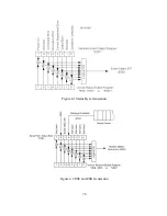
Page 88: ...Figure 4 1 Status Byte Generation Figure 4 2 ESE and ESR Generation 76...
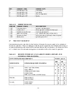
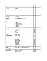
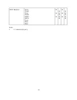
Page 95: ...IEEE Standard CLS ESR ESE STB SRE IDN SAV RCL RST Notes 1 C command Q query 83...
Page 97: ...Figure 5 1 Configuration setup Figure 5 2 GPIB communications setup 85...
Page 99: ...Figure 5 4 Virtual Control Panel Figure 5 5 Command Panel 87...
Page 102: ...Figure 5 7 Calibration Panel Figure 5 8 Firmware Panel 90...
Page 103: ...Figure 5 9 Modulation Panel 91...
Page 123: ...Figure B 1 Information Panel Figure B 2 Configure Panel 111...
Page 124: ...Figure B 3 Reboot in Progress Panel Figure B 4 Web Control Panel 112...


