


Table, which is stored in RAM, loses its data on power down cycles. This command allows this
data to be recovered at the power on cycle.
Command Syntax:
MOD:SAVE
MODulation:TABLe:SAVE
Examples: MOD:SAVE
Query Syntax:
None
Returned Parameters: None
Related Commands: MOD:TABL:LOAD
4.3.14.4 MOD:TABL:LOAD
This command copies all data stored in the Cache Table to the Active Table. The command
provides two optional parameters for initiating the activate set points for voltage and current. The
command lets users quickly load tables and simultaneous change the power supply’s output
operating point.
Command Syntax:
MOD:TABL:LOAD [<NRf>, <NRf>]
Examples:
MOD:TABL:LOAD
MODulation:TABLe:LOAD
MODulation:TABL:LOAD 93.4, 30.3
Query Syntax:
None
Returned Parameters: None
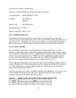
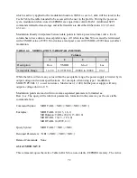
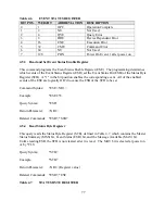
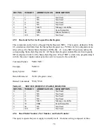
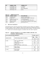
4.3.15 SCPI Data Formats
All data programmed to or returned from the power supply are formatted in ASCII. The data may
be structured as numerical or character string as described in Table 4.5.
Table 4.5
SCPI DATA FORMATS
FORMAT
DESCRIPTON
EXAMPLES
<>
Null, no data.
<NR1>
Digits with an implied decimal point assumed at the right of
the least-significant digit.
-273
0273
<NR2>
Digits with an explicit decimal point.
273.
.0273
<NR3>
Digits with an explicit decimal point and an exponent
2.73E+2
73
Summary of Contents for XR III series
Page 1: ...OPERATING AND SERVICE MANUAL XR SERIES III DC POWER SUPPLIES...
Page 2: ......
Page 3: ...MAGNA POWER ELECTRONICS INC 39 ROYAL ROAD FLEMINGTON NJ 08822 February 20 2012...
Page 4: ......
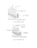
Page 88: ...Figure 4 1 Status Byte Generation Figure 4 2 ESE and ESR Generation 76...
Page 95: ...IEEE Standard CLS ESR ESE STB SRE IDN SAV RCL RST Notes 1 C command Q query 83...
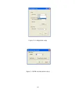
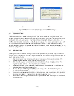
Page 97: ...Figure 5 1 Configuration setup Figure 5 2 GPIB communications setup 85...
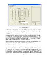
Page 99: ...Figure 5 4 Virtual Control Panel Figure 5 5 Command Panel 87...
Page 102: ...Figure 5 7 Calibration Panel Figure 5 8 Firmware Panel 90...
Page 103: ...Figure 5 9 Modulation Panel 91...
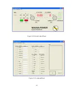
Page 123: ...Figure B 1 Information Panel Figure B 2 Configure Panel 111...
Page 124: ...Figure B 3 Reboot in Progress Panel Figure B 4 Web Control Panel 112...


