


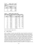

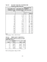


8.3 illustrates the different charging steps and Table 8.4 provides the recommended charging
voltage per cell for different battery technologies.
Diode D1 with associated remote sense connections can be avoided with application of the high-
slew rate option. As compared to standard XR Series models, the high-slew rate option has less
output capacitance and less loading on the battery when the power supply is off. Appendix 8.6
discusses the benefits of this option.
Caution: All battery parameters presented in this section are guidelines and the
user should refer to and use manufacturer’s specifications in any battery
charging application.
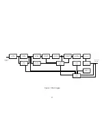
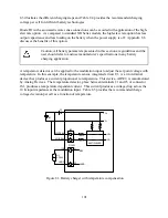
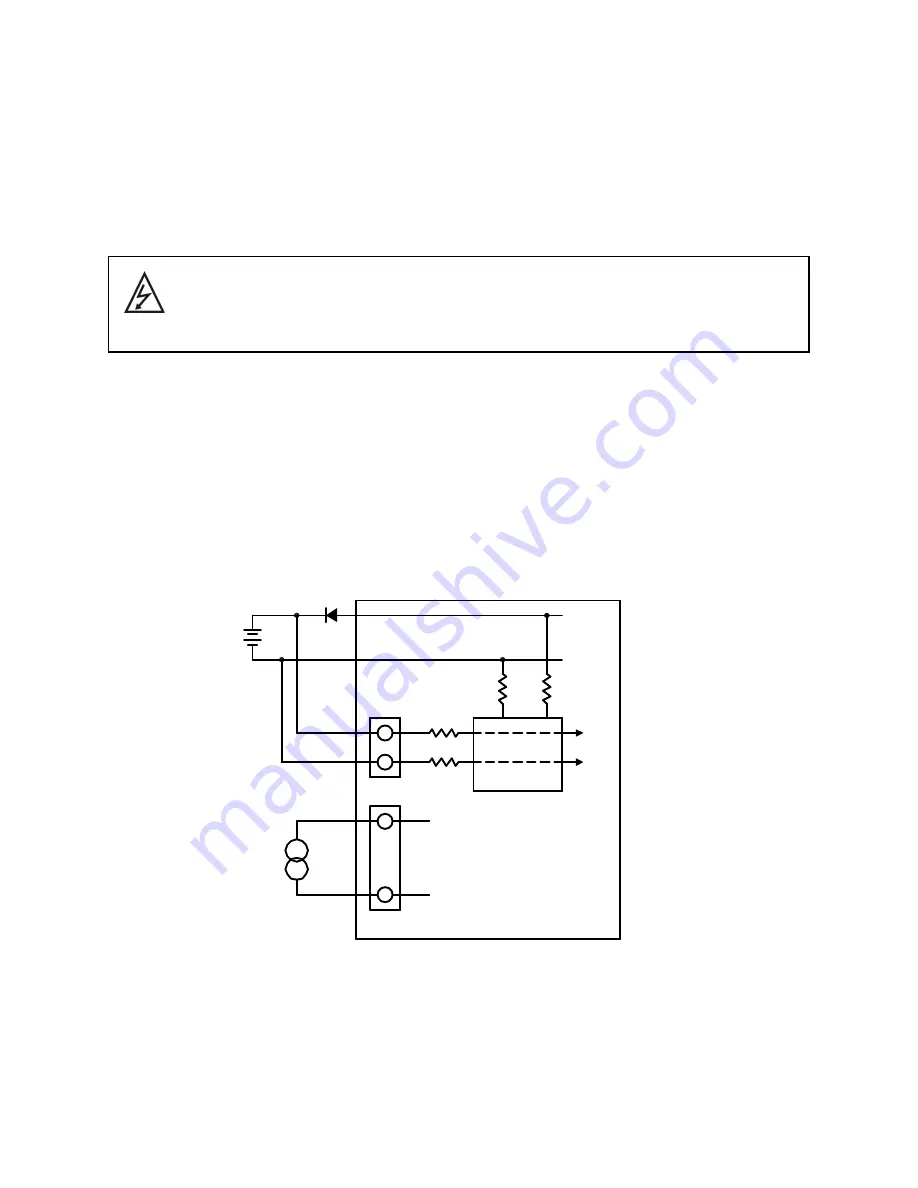
A temperature detector can be applied to the modulation input to adjust the set point voltage with
temperature. In this example, the temperature sensor, integrated circuit U1, is a two terminal
device that produces a current proportional to temperature. This device, AD592, is manufactured
by Analog Devices. The temperature detector, place between terminals 21 and 25 of connector
JS1, produces a temperature dependent current. This current produces a voltage drop across the
10 K input impedance at the modulation input. Table 8.5 provides the recommended charge
voltage deviation per cell as a function of temperature.
Figure 8.3 Battery charger with temperature compensation
VMOD
P/O JS1
25
21
IO2
REF
AD592
U1
+
-
VO1REM-
VS-
VS+
1
2
JS2
B1
VO-
VO+
MULTIPLEXER
D1
VMOD
101
Summary of Contents for XR III series
Page 1: ...OPERATING AND SERVICE MANUAL XR SERIES III DC POWER SUPPLIES...
Page 2: ......
Page 3: ...MAGNA POWER ELECTRONICS INC 39 ROYAL ROAD FLEMINGTON NJ 08822 February 20 2012...
Page 4: ......
Page 88: ...Figure 4 1 Status Byte Generation Figure 4 2 ESE and ESR Generation 76...
Page 95: ...IEEE Standard CLS ESR ESE STB SRE IDN SAV RCL RST Notes 1 C command Q query 83...
Page 97: ...Figure 5 1 Configuration setup Figure 5 2 GPIB communications setup 85...
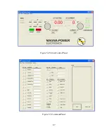
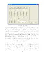
Page 99: ...Figure 5 4 Virtual Control Panel Figure 5 5 Command Panel 87...
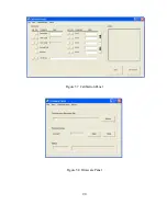
Page 102: ...Figure 5 7 Calibration Panel Figure 5 8 Firmware Panel 90...
Page 103: ...Figure 5 9 Modulation Panel 91...
Page 123: ...Figure B 1 Information Panel Figure B 2 Configure Panel 111...
Page 124: ...Figure B 3 Reboot in Progress Panel Figure B 4 Web Control Panel 112...


