


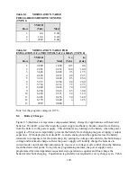


Table 8.1
MODULATION TABLE
FOR LEADLESS REMOTE SENSING
(TYPE 1)
Row
VMOD
(Vdc)
Mod
1
2
3
0.0
10.0
9999
0.00
0.20
0.00
Table 8.2
MODULATION TABLE FOR
EMULATION OF A PHOTOVOLTAIC ARRAY (TYPE 0)
Row
VMOD
(Vdc)
Mod
Vo
(Vdc)
Io
(Adc)
1
2
3
4
5
6
7
8
9
10
11
12
13
0.000
2.085
3.645
4.690
5.210
5.415
5.730
6.040
6.250
6.460
6.665
6.770
9999
1.000
0.952
0.905
0.857
0.809
0.762
0.714
0.666
0.619
0.571
0.476
0.000
0.000
105
100
95
90
85
80
75
70
65
60
50
0
0.0
10.0
17.5
22.5
25.0
26.0
27.5
29.0
30.0
31.0
32.0
32.5
Note: Set the program voltage to 105 V.
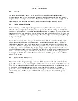
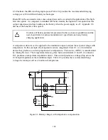
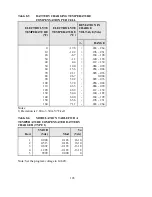
8.4
Battery Charger
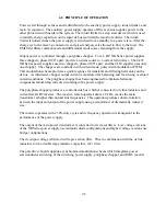
Figure 8.3 illustrates a temperature compensated battery charger for applications with lead acid
batteries. Diode D1, placed between the power supply and battery, blocks current from flowing
from the battery to the power supply. This eliminates any loading on the battery when the power
supply is off, but more importantly, prevents the battery from charging the power supply’s output
capacitors. With deployment of diode D1, remote sensing should be applied across the battery
terminals to compensate for the diode drop. By setting the voltage and current to the bulk charge
voltage and maximum charge current, the power supply will initially charge the batteries in
current mode control and then automatically crossover to voltage mode control when the batteries
reach the desired set point. Using remote programming features, the power supply can be
programmed for time dependent, sequential step operation to equalize and float charge the
batteries after bulk charging. Equalization is generally not required for every charge cycle. Table
100
Summary of Contents for XR III series
Page 1: ...OPERATING AND SERVICE MANUAL XR SERIES III DC POWER SUPPLIES...
Page 2: ......
Page 3: ...MAGNA POWER ELECTRONICS INC 39 ROYAL ROAD FLEMINGTON NJ 08822 February 20 2012...
Page 4: ......
Page 88: ...Figure 4 1 Status Byte Generation Figure 4 2 ESE and ESR Generation 76...
Page 95: ...IEEE Standard CLS ESR ESE STB SRE IDN SAV RCL RST Notes 1 C command Q query 83...
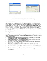
Page 97: ...Figure 5 1 Configuration setup Figure 5 2 GPIB communications setup 85...
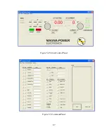
Page 99: ...Figure 5 4 Virtual Control Panel Figure 5 5 Command Panel 87...
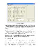
Page 102: ...Figure 5 7 Calibration Panel Figure 5 8 Firmware Panel 90...
Page 103: ...Figure 5 9 Modulation Panel 91...
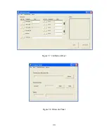
Page 123: ...Figure B 1 Information Panel Figure B 2 Configure Panel 111...
Page 124: ...Figure B 3 Reboot in Progress Panel Figure B 4 Web Control Panel 112...


