


7.3
Calibration
7.3.1 Control Board
The control board contains digital potentiometers for fine adjustments of the reference and
feedback amplifiers. These potentiometers may be adjusted by using the front panel controls
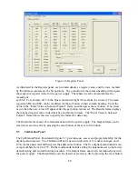
described in Section 3.1.4. These potentiometers can also be adjusted by using the Calibration
Panel of the Remote Interface Software described in Section 5.5.
7.3.1.1 Reference Amplifier Calibration
Connect a voltmeter between terminal 6 of JS1 (positive) and terminal 1 of JS1 (negative). With
only the control power applied, adjust potentiometer P5 for a 2.5006 V.
7.3.1.2 Voltage Feedback Amplifier Calibration
Place a dc voltmeter across the output terminals of the power supply and place a second dc
voltmeter to monitor VO2, the voltage between terminal 5 of JS1 (positive) and terminal 1 of JS1
(negative). Set the load to 50% rated output current at full scale voltage.
With only the control power applied, adjust potentiometer P2 for 0.000 V at VO2. Using the
up/down (V/I DIS or TRIP DIS) keys or RS232 remote interface, set the output voltage to 50%
full scale output. Turn on the power supply and adjust potentiometer P1 until the output voltage
matches the set point voltage. Now set the output voltage to its full scale rating and measure the
output voltage. Adjust potentiometer P1 to equally divide the error between the half scale set
point and the full scale point.
7.3.1.3 Current Feedback Amplifier Calibration
Place a dc ammeter in series with the load of the power supply and place a dc voltmeter to
monitor IO2, the voltage between terminal 24 of JS1 (positive) and terminal 1 of JS1 (negative).
Set the load to 100% rated output current at 90 % full scale voltage.
With only the control power applied, adjust potentiometer P4 for 0.000 V at IO2. Using the
up/down (V/I DIS or TRIP DIS) keys or RS232 remote interface, set the output current to 50%
full scale output. Turn on the power supply and adjust potentiometer P3 until the output current
matches the set point current. Now set the output current to its full scale rating and measure the
output current. Adjust potentiometer P3 to equally divide the error between the half scale set
point and the full scale point.
7.3.2 Driver Board
The driver board contains two potentiometers which are used to set under voltage and over
current protection in the polyphase chopper circuitry. These potentiometer do not normally need
adjustment in the field.
96
Summary of Contents for XR III series
Page 1: ...OPERATING AND SERVICE MANUAL XR SERIES III DC POWER SUPPLIES...
Page 2: ......
Page 3: ...MAGNA POWER ELECTRONICS INC 39 ROYAL ROAD FLEMINGTON NJ 08822 February 20 2012...
Page 4: ......
Page 88: ...Figure 4 1 Status Byte Generation Figure 4 2 ESE and ESR Generation 76...
Page 95: ...IEEE Standard CLS ESR ESE STB SRE IDN SAV RCL RST Notes 1 C command Q query 83...
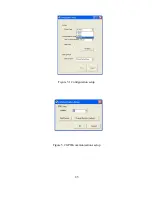
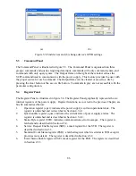
Page 97: ...Figure 5 1 Configuration setup Figure 5 2 GPIB communications setup 85...
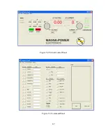
Page 99: ...Figure 5 4 Virtual Control Panel Figure 5 5 Command Panel 87...
Page 102: ...Figure 5 7 Calibration Panel Figure 5 8 Firmware Panel 90...
Page 103: ...Figure 5 9 Modulation Panel 91...
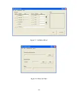
Page 123: ...Figure B 1 Information Panel Figure B 2 Configure Panel 111...
Page 124: ...Figure B 3 Reboot in Progress Panel Figure B 4 Web Control Panel 112...


