


XR Series models have extensive diagnostic functions -- all of which when activated take
command to shut down the system. Diagnostic functions include phase loss, excessive thermal
conditions, over voltage trip, over current trip, and program line. Program line monitors
externally applied analog set point signals to insure they are within the specified range. Upon a
diagnostic fault condition, main power is disconnected and the diagnostic condition is latched
into memory. Pressing the clear key clears the memory. All diagnostic functions can be
monitored through a rear connector. Furthermore, control functions can also be set through the
rear connector to allow simultaneous control of one or more XR Series units.
1.3
IEC Symbols Used in Manual
The following IEC symbols are used in this manual.
Caution, risk of electric shock
Caution, risk of danger
Protective conductor terminal
Three-phase alternating current
1.4
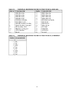
Power Requirements
XR Series power supplies are manufactured to operate on 208/240 V, 380/415 V, or 440/480 V
50 to 400 Hz mains.
The standard operating voltage is 208 V, 3
φ
, 50 to 400 Hz unless otherwise specified at time of
order. For conversion from 208 V to 240 V operation, two internal wiring changes must be
made. The locations are not accessible to the user and the power supply must be returned to the
factory for modification.
XR Series power supplies are optionally available to operate on 380 V or 480 V, 3
φ
, 50 to 400
Hz mains. For conversion from 380 V to 415 V or from 480 V to 440 V operation, two internal
wiring changes must be made. The locations are not accessible to the user and the power supply
must be returned to the factory for modification.
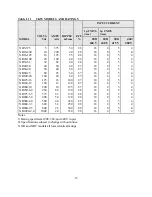
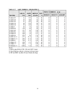
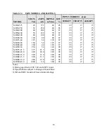
1.5
Specifications
The following specifications describe the published operational characteristics of the XR Series
power supplies.
4
Summary of Contents for XR III series
Page 1: ...OPERATING AND SERVICE MANUAL XR SERIES III DC POWER SUPPLIES...
Page 2: ......
Page 3: ...MAGNA POWER ELECTRONICS INC 39 ROYAL ROAD FLEMINGTON NJ 08822 February 20 2012...
Page 4: ......
Page 88: ...Figure 4 1 Status Byte Generation Figure 4 2 ESE and ESR Generation 76...
Page 95: ...IEEE Standard CLS ESR ESE STB SRE IDN SAV RCL RST Notes 1 C command Q query 83...
Page 97: ...Figure 5 1 Configuration setup Figure 5 2 GPIB communications setup 85...
Page 99: ...Figure 5 4 Virtual Control Panel Figure 5 5 Command Panel 87...
Page 102: ...Figure 5 7 Calibration Panel Figure 5 8 Firmware Panel 90...
Page 103: ...Figure 5 9 Modulation Panel 91...
Page 123: ...Figure B 1 Information Panel Figure B 2 Configure Panel 111...
Page 124: ...Figure B 3 Reboot in Progress Panel Figure B 4 Web Control Panel 112...


