
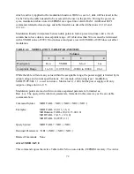
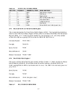

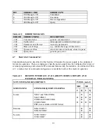


BIT
ERROR CODE
ERROR TYPE
5
100 through -199
Command
4
200 through -299
Execution
3
300 through -399
Device dependent
2
400 through -499
Query
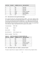
Table 4.10
ERROR MESSAGES
ERROR
ERROR STRING
DESCRIPTION
-100
Command error
generic command error
-102
Syntax error
unrecognized command or data type
-108
Parameter not allowed
too many parameters
-222
Data out of range
e.g., outside the range of this device
-350
Queue overflow
errors lost due to too many errors in queue
-400
Query error
generic query error
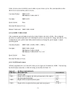
4.7
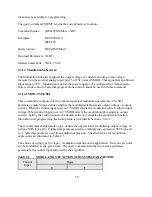
Restricted Command Set
Commands and queries described in this Section 4.0 require the power supply to be configured
for remote operation. There are instances when the power supply may be configured for rotary or
external programming and certain SCPI command features may be desirable. As defined in Table
4.11, a reduced set of commands and queries are available to allow this mode of operation.
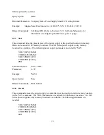
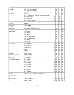
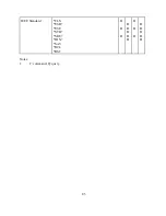
Table 4.11
REMOTE INTERFACE AVAILABILITY DURING ROTARY AND
EXTERNAL PROGRAMMING
SCPI COMMAND DESCRIPTION
PANEL (note 1)
SUBSYSTEM
COMMAND/QUERY EXAMPLE
XRC
XR
C
Q
C
Q
Source
VOLT and VOLT:TRIG
VOLT:PROT
CURR and CURR:TRIG
CURR:PROT
PER (not available with XR Series)
!
!
!
!
!
!
!
!
!
!
!
!
Measure
MEAS:VOLT?
MEAS:CURR?
!
!
!
!
System
SYST:VERS?
SYST:ERR?
!
!
!
!
81
Summary of Contents for XR III series
Page 1: ...OPERATING AND SERVICE MANUAL XR SERIES III DC POWER SUPPLIES...
Page 2: ......
Page 3: ...MAGNA POWER ELECTRONICS INC 39 ROYAL ROAD FLEMINGTON NJ 08822 February 20 2012...
Page 4: ......
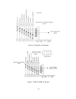
Page 88: ...Figure 4 1 Status Byte Generation Figure 4 2 ESE and ESR Generation 76...
Page 95: ...IEEE Standard CLS ESR ESE STB SRE IDN SAV RCL RST Notes 1 C command Q query 83...
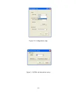
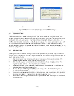
Page 97: ...Figure 5 1 Configuration setup Figure 5 2 GPIB communications setup 85...
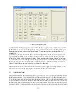
Page 99: ...Figure 5 4 Virtual Control Panel Figure 5 5 Command Panel 87...
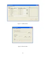
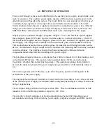
Page 102: ...Figure 5 7 Calibration Panel Figure 5 8 Firmware Panel 90...
Page 103: ...Figure 5 9 Modulation Panel 91...
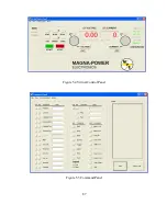
Page 123: ...Figure B 1 Information Panel Figure B 2 Configure Panel 111...
Page 124: ...Figure B 3 Reboot in Progress Panel Figure B 4 Web Control Panel 112...


