


273.0E-2
<NRf>
Extended format that includes <NR1>, <NR2> and <NR3>.
273
-273.0
2.73E2
<NRf+>
Expanded decimal format that includes <NRf>, MIN, and
MAX
273
-273
2.73E2
MIN
MAX
4.4
IEEE-488 Event Processing
All of the SCPI subsystem commands in the previous section can be initiated using RS232,
optional IEEE-488, or optional Ethernet communications.
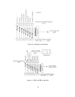
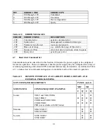
The IEEE-488 standard defines a method for status reporting. As illustrated in figure 4.1, the
method uses the IEEE-488.1 Status Byte (STB). Three bits of this byte are defined as: Master
Status Summary (MSS) Bit, Event Status Bit (ESB), and Message Available (MAV) Bit.
The Master Status Summary (MSS) is an unlatched bit. When the Status Byte Register is read
using a Status Byte Register query (discussed in Section 4.5.4), bit 6 will be 1 if there are any
conditions requiring service.
The STB is masked by the Service Request Enable Register (SRE) to allow the user to mask
specific or all events from setting the MSS bit to 1. The MSS bit is obtained by logical OR’ing
the bits of the enabled Status Byte Register.
The Event Status Bit (ESB) is set when one of the events defined in the Event Status Register
(ESR) (see Table 4.6) has occurred. As shown in figure 4.2 and like the STB, the ESR is masked
by the Event Status Enable Register (ESE) to allow the user to mask specific or all events from
setting the ESB to 1.
The Message AVailable (MAV) bit is set to 1 when a message is available in the output buffer.
4.5
IEEE-488 Standard Commands
The following sections describe the IEEE-488 Standard Commands.
4.5.1 Clear
This command clears all status register (ESR, STB and error queue).
Command Syntax:
*CLS <>
74
Summary of Contents for XR III series
Page 1: ...OPERATING AND SERVICE MANUAL XR SERIES III DC POWER SUPPLIES...
Page 2: ......
Page 3: ...MAGNA POWER ELECTRONICS INC 39 ROYAL ROAD FLEMINGTON NJ 08822 February 20 2012...
Page 4: ......
Page 88: ...Figure 4 1 Status Byte Generation Figure 4 2 ESE and ESR Generation 76...
Page 95: ...IEEE Standard CLS ESR ESE STB SRE IDN SAV RCL RST Notes 1 C command Q query 83...
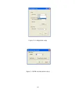
Page 97: ...Figure 5 1 Configuration setup Figure 5 2 GPIB communications setup 85...
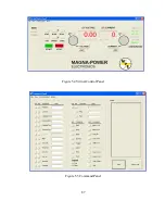
Page 99: ...Figure 5 4 Virtual Control Panel Figure 5 5 Command Panel 87...
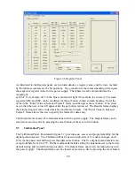
Page 102: ...Figure 5 7 Calibration Panel Figure 5 8 Firmware Panel 90...
Page 103: ...Figure 5 9 Modulation Panel 91...
Page 123: ...Figure B 1 Information Panel Figure B 2 Configure Panel 111...
Page 124: ...Figure B 3 Reboot in Progress Panel Figure B 4 Web Control Panel 112...


