


Caution: No plus or minus voltage should exceed 1000 Vdc with respect to
ground.
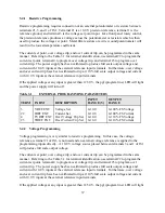
3.9.1 Series Operation - Direct
The simplest series connection involves attaching the positive terminal of the first supply to the
negative terminal of the second supply. The load is connected between the negative terminal of
the first supply and the positive terminal of the second supply. The output current controls of
each power supply are operative and the current limit is equal to the lowest control setting. If any
one output current control is set too low with respect to the total output current, the series power
supplies will automatically crossover to constant current operation and the output voltage will
drop.
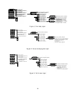
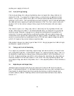
3.9.2 Series Operation - Master/Slave
Master/slave series operation permits equal voltage sharing under all load conditions and allows
complete control of output voltage from one master power supply.
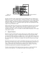
Figure 3.18 illustrates the terminal connection for master/slave series operation and salient control
circuitry. The control cable can be fabricated by the user or purchased as an option, UID46, from
the factory. These connections perform the following functions:
1.
The voltage monitoring voltage, VO2, on the master power supply connects to the
external voltage set point input on the slave power supply. This makes the slave
power supply operate at the same voltage output as the master power supply
2.
The power output digital control line of the master power supply connects to the
start digital control line of the slave power supply. This connection causes the
slave unit to turn on when the master unit is turned on.
3.
The standby/alm digital control line of the master power supply connects to the
stop digital control line of the slave power supply. This connection causes the
slave unit to turn off when the master unit is turned off or when a diagnostic
condition appears.
4.
Connections between terminals 4, 21, 22, and 23 set the current control to
maximum and set over voltage trip and over current trip to set points just beyond
full scale values. This forces the slave power supply to operate simply as a voltage
source whose voltage set point is established by the master unit.
The slave power supply must be configured for external program input. The master unit can
configured for rotary, external program, or remote input. Configuration commands are discussed
in Section 3.1.3.
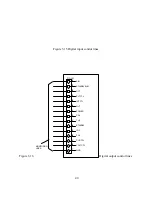
To add a second slave unit, connect the output terminals of the second slave in series with the
other two power supplies. Furthermore, connect a second control cable between the second slave
44
Summary of Contents for XR III series
Page 1: ...OPERATING AND SERVICE MANUAL XR SERIES III DC POWER SUPPLIES...
Page 2: ......
Page 3: ...MAGNA POWER ELECTRONICS INC 39 ROYAL ROAD FLEMINGTON NJ 08822 February 20 2012...
Page 4: ......
Page 88: ...Figure 4 1 Status Byte Generation Figure 4 2 ESE and ESR Generation 76...
Page 95: ...IEEE Standard CLS ESR ESE STB SRE IDN SAV RCL RST Notes 1 C command Q query 83...
Page 97: ...Figure 5 1 Configuration setup Figure 5 2 GPIB communications setup 85...
Page 99: ...Figure 5 4 Virtual Control Panel Figure 5 5 Command Panel 87...
Page 102: ...Figure 5 7 Calibration Panel Figure 5 8 Firmware Panel 90...
Page 103: ...Figure 5 9 Modulation Panel 91...
Page 123: ...Figure B 1 Information Panel Figure B 2 Configure Panel 111...
Page 124: ...Figure B 3 Reboot in Progress Panel Figure B 4 Web Control Panel 112...


