


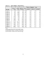


Table 1.1
COMPARISON CHART OF FRONT AND REAR
PANEL CONTROLS AND INDICATORS
Features
MODELS
XRC
XR
FRONT PANEL CONTROLS
Power on/off
Start/Stop
Rotary voltage/current entry
Menu/Item
Display settings
Enter/Clear
INDICATORS
Voltage/current set point
OVT/OCT set point
Voltage/current output
Internal/external control
Alarms
Rotary/external/remote programming
Remote sense enabled
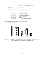
REAR PANEL CONTROLS
Voltage/current set point
OVT/OCT set point
Modulation set point
Voltage/current output
Internal/external control
Alarm outputs (8 lines)
Status outputs (6 lines)
Master/Slave connections
Remote sense inputs
RS232 inputs/outputs
Optional IEEE-488 inputs/outputs
Optional Ethernet inputs/outputs
Interlock enable
!
!
!
!
!
!
!
!
!
!
!
!
!
!
!
!
!
!
!
!
!
!
!
!
!
!
!
!
!
!
!
!
!
!
!
!
!
!
!
!
3
Summary of Contents for XR III series
Page 1: ...OPERATING AND SERVICE MANUAL XR SERIES III DC POWER SUPPLIES...
Page 2: ......
Page 3: ...MAGNA POWER ELECTRONICS INC 39 ROYAL ROAD FLEMINGTON NJ 08822 February 20 2012...
Page 4: ......
Page 88: ...Figure 4 1 Status Byte Generation Figure 4 2 ESE and ESR Generation 76...
Page 95: ...IEEE Standard CLS ESR ESE STB SRE IDN SAV RCL RST Notes 1 C command Q query 83...
Page 97: ...Figure 5 1 Configuration setup Figure 5 2 GPIB communications setup 85...
Page 99: ...Figure 5 4 Virtual Control Panel Figure 5 5 Command Panel 87...
Page 102: ...Figure 5 7 Calibration Panel Figure 5 8 Firmware Panel 90...
Page 103: ...Figure 5 9 Modulation Panel 91...
Page 123: ...Figure B 1 Information Panel Figure B 2 Configure Panel 111...
Page 124: ...Figure B 3 Reboot in Progress Panel Figure B 4 Web Control Panel 112...


