


Examples: VOLT
200
VOLTAGE:LEVEL 200
VOLTAGE:LEVEL:IMMEDIATE:AMPLITUDE 2.5
VOLT:TRIG MAX
VOLTAGE:LEVEL:TRIGGERED 20
Query Syntax:
[SOURce]:VOLTage[:LEVel][:IMMediate][:AMPLitude]?
[SOURce]:VOLTage[:LEVel][:IMMediate][:AMPLitude]? MAX
[SOURce]:VOLTage[:LEVel][:IMMediate][:AMPLitude]? MIN
[SOURce]:VOLTage[:LEVel]:TRIGgered[:AMPLitude]?
[SOURce]:VOLTage[:LEVel]:TRIGgered[:AMPLitude]? MAX
[SOURce]:VOLTage[:LEVel]:TRIGgered[:AMPLitude]? MIN
Returned Parameter: <NR2>
Related Commands (for VOLT):
*SAV, *RCL, *RST
Related Commands (for VOLT:TRIG):
ABOR, VOLT, *RST
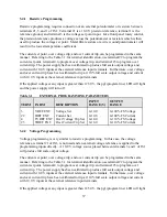
4.3.1.2 VOLT:PROT
This command sets the over voltage trip (OVT) level of the power supply. If the output voltage
exceeds the OVT level, then the power supply output is disabled and the Questionable Condition
status register OV bit is set (see Table 4.2). An over voltage trip condition can be cleared with
the OUTP:PROT:CLE command after the condition that caused the OVT trip is removed.
VOLT:PROT? returns presently programmed OVT level. VOLT:PROT? MAX and
VOLT:PROT? MIN return the maximum and minimum programmable OVT levels.
Command Syntax:
[SOURce]:VOLTage:PROTection[:LEVel] <NRf+>
Examples: VOLT:PROT
21.5
VOLTAGE:PROTECTION:LEVEL 145E-1
Query Syntax:
[SOURce]:VOLTage:PROTection[:LEVel]?
[SOURce]:VOLTage:PROTection[:LEVel]? MIN
[SOURce]:VOLTage:PROTection[:LEVel]? MAX
Returned Parameter: <NR2>
Related Commands: OUTP:PROT:CLE, *RST, *SAV, *RCL
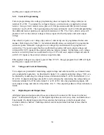
4.3.1.3 CURR and CURR:TRIG
These commands set the immediate current level or the pending triggered current level of the
power supply. The immediate level is the current programmed for the power supply output. The
51
Summary of Contents for XR III series
Page 1: ...OPERATING AND SERVICE MANUAL XR SERIES III DC POWER SUPPLIES...
Page 2: ......
Page 3: ...MAGNA POWER ELECTRONICS INC 39 ROYAL ROAD FLEMINGTON NJ 08822 February 20 2012...
Page 4: ......
Page 88: ...Figure 4 1 Status Byte Generation Figure 4 2 ESE and ESR Generation 76...
Page 95: ...IEEE Standard CLS ESR ESE STB SRE IDN SAV RCL RST Notes 1 C command Q query 83...
Page 97: ...Figure 5 1 Configuration setup Figure 5 2 GPIB communications setup 85...
Page 99: ...Figure 5 4 Virtual Control Panel Figure 5 5 Command Panel 87...
Page 102: ...Figure 5 7 Calibration Panel Figure 5 8 Firmware Panel 90...
Page 103: ...Figure 5 9 Modulation Panel 91...
Page 123: ...Figure B 1 Information Panel Figure B 2 Configure Panel 111...
Page 124: ...Figure B 3 Reboot in Progress Panel Figure B 4 Web Control Panel 112...


