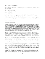
0.04 %/
E
C of maximum output voltage,
0.06 %/
E
C of maximum output current.
Isolation:
User inputs and outputs: referenced to earth ground,
Maximum input voltage to ground: ±2500 Vac,
Maximum output voltage to ground: ±1000 Vdc.
Power Factor:
greater than 92% at maximum power, 3
φ
inputs,
greater than 70% at maximum power for 1
φ
inputs.
Ambient Temperature:
0 to 50
E
C.
Storage Temperature:
-25 to +85
E
C.
Remote sense limits:
3% maximum voltage drop from output terminals to load.
Remote analog programming limits:
Voltage set point: 0 to 10.0 Vdc for 0 to 100% output,
Current set point: 0 to 10.0 Vdc for 0 to 100% output,
Over voltage trip set point: 0 to 10.0 Vdc for 0 to 110% output,
Over current trip set point: 0 to 10.0 Vdc for 0 to 110% output,
Modulation: 0 to 10 Vdc.
Remote analog input impedance:
10K for all inputs.
Remote analog programming accuracy of full scale:
Voltage set point: ±0.075%,
Current set point: ±0.075%,
Over voltage trip set point: ±0.075%,
Over current trip set point: ±0.075%.
Analog monitoring and reference:
Output voltage: 0 to 10.0 Vdc, 5 mA,
Output current: 0 to 10.0 Vdc, 5 mA,
+10V Ref: 10.0 Vdc, 5 mA,
Analog output impedances:
Voltage output monitoring: 100 ohm,
Current output monitoring: 100 ohm,
+10V Ref: 1 ohm.
Analog monitoring accuracy of full scale:
Output voltage: ±0.2%,
6
Summary of Contents for XR III series
Page 1: ...OPERATING AND SERVICE MANUAL XR SERIES III DC POWER SUPPLIES...
Page 2: ......
Page 3: ...MAGNA POWER ELECTRONICS INC 39 ROYAL ROAD FLEMINGTON NJ 08822 February 20 2012...
Page 4: ......
Page 88: ...Figure 4 1 Status Byte Generation Figure 4 2 ESE and ESR Generation 76...
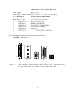
Page 95: ...IEEE Standard CLS ESR ESE STB SRE IDN SAV RCL RST Notes 1 C command Q query 83...
Page 97: ...Figure 5 1 Configuration setup Figure 5 2 GPIB communications setup 85...
Page 99: ...Figure 5 4 Virtual Control Panel Figure 5 5 Command Panel 87...
Page 102: ...Figure 5 7 Calibration Panel Figure 5 8 Firmware Panel 90...
Page 103: ...Figure 5 9 Modulation Panel 91...
Page 123: ...Figure B 1 Information Panel Figure B 2 Configure Panel 111...
Page 124: ...Figure B 3 Reboot in Progress Panel Figure B 4 Web Control Panel 112...


