


4.3.12.3 NET:SER? (Optional Ethernet only)
This command sets the serial number of the Ethernet module. The serial number is an integer
ranging from 1 to 16777215 and cannot be altered by the user
.
Query Syntax:
[SYSTem][:COMMunicate]:NETwork:SER?
Parameters: None
Examples: SYST:COMM:NET:SER?
NET:SER?
Returned Parameters: <integer>
Related Commands: none
4.3.12.4 NET:ADDR (Optional Ethernet only)
This command sets the static address of the Ethernet module of the power supply. The factory
default address setting is 192.168.1.100.
Command Syntax:
[SYSTem][:COMMunicate]:NETwork:ADDRess <string>
Parameters:
IP address is represented with 4 bytes each having a range of 0-255
separated by dots
Examples: SYSTem:COMM:NET:ADDR
192.168.10.2
NET:ADDR 192.168.10.2
Query Syntax:
[SYSTem][:COMMunicate]:NETwork:ADDR?
Returned Parameters: <string>
Related Commands: NET:MAC, NET:GATE, NET:SUBN, NET:PORT, NET:HOST,
NET:DHCP
4.3.12.5 NET:GATE (Optional Ethernet only)
This command sets the Gateway IP address of the Ethernet module of the power supply. The
factory default Gateway IP setting is 192.168.1.1.
Command Syntax:
[SYSTem][:COMMunicate]:NETwork:GATE <string>
Parameters:
Gateway IP address is represented with 4 bytes each having a range of 0-
255 separated by dots
67
Summary of Contents for XR III series
Page 1: ...OPERATING AND SERVICE MANUAL XR SERIES III DC POWER SUPPLIES...
Page 2: ......
Page 3: ...MAGNA POWER ELECTRONICS INC 39 ROYAL ROAD FLEMINGTON NJ 08822 February 20 2012...
Page 4: ......
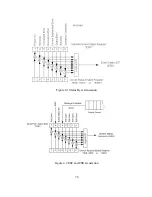
Page 88: ...Figure 4 1 Status Byte Generation Figure 4 2 ESE and ESR Generation 76...
Page 95: ...IEEE Standard CLS ESR ESE STB SRE IDN SAV RCL RST Notes 1 C command Q query 83...
Page 97: ...Figure 5 1 Configuration setup Figure 5 2 GPIB communications setup 85...
Page 99: ...Figure 5 4 Virtual Control Panel Figure 5 5 Command Panel 87...
Page 102: ...Figure 5 7 Calibration Panel Figure 5 8 Firmware Panel 90...
Page 103: ...Figure 5 9 Modulation Panel 91...
Page 123: ...Figure B 1 Information Panel Figure B 2 Configure Panel 111...
Page 124: ...Figure B 3 Reboot in Progress Panel Figure B 4 Web Control Panel 112...


