


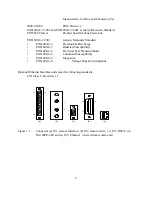


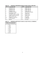


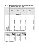


Table 1.8
TERMINAL DEFINITIONS FOR CONNECTOR JS4, IEEE-488
TERM
PARAMETER
TERM
PARAMETER
1
2
3
4
5
6
7
8
9
10
11
12
DIO1/Data line
DIO2/Data line
DIO3/Data line
DIO4/Data line
EOI/End or Identify
DAV/Data Valid
NRFD/Not Ready For Data
NDAC/Not Data Accepted
IFC/Interface Clear
SRQ/Service Request
ATN/Attention
Shield
13
14
15
16
17
18
19
20
21
22
23
24
DIO5/Data line
DIO6/Data line
DIO7/Data line
DIO8/Data line
REN/Remote Enable
DAV/Gnd
NRFD/Gnd
NDAC/Gnd
IFC/Gnd
SRQ/Gnd
ATN/Gnd
Ground
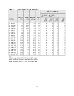
Table 1.9
TERMINAL DEFINITIONS FOR CONNECTOR JS5, ETHERNET
TERM PARAMETER
1
2
3
4
5
6
7
8
TX+
TX-
RX+
NC
NC
RX-
NC
NC
11
Summary of Contents for XR III series
Page 1: ...OPERATING AND SERVICE MANUAL XR SERIES III DC POWER SUPPLIES...
Page 2: ......
Page 3: ...MAGNA POWER ELECTRONICS INC 39 ROYAL ROAD FLEMINGTON NJ 08822 February 20 2012...
Page 4: ......
Page 88: ...Figure 4 1 Status Byte Generation Figure 4 2 ESE and ESR Generation 76...
Page 95: ...IEEE Standard CLS ESR ESE STB SRE IDN SAV RCL RST Notes 1 C command Q query 83...
Page 97: ...Figure 5 1 Configuration setup Figure 5 2 GPIB communications setup 85...
Page 99: ...Figure 5 4 Virtual Control Panel Figure 5 5 Command Panel 87...
Page 102: ...Figure 5 7 Calibration Panel Figure 5 8 Firmware Panel 90...
Page 103: ...Figure 5 9 Modulation Panel 91...
Page 123: ...Figure B 1 Information Panel Figure B 2 Configure Panel 111...
Page 124: ...Figure B 3 Reboot in Progress Panel Figure B 4 Web Control Panel 112...


